
Quantum cipher communication system and method of setting average photon number at communication terminal

a communication system and quantum cipher technology, applied in the direction of secret communication, digital transmission, synchronising transmission/receiving encryption devices, etc., can solve problems such as difficulty in distributing keys, and achieve the effect of easy detection of wiretap

Inactive Publication Date: 2007-10-25
SONY CORP
View PDF18 Cites 15 Cited by
  • Summary
  • Abstract
  • Description
  • Claims
  • Application Information

AI Technical Summary

Benefits of technology

[0011] It may be desirable to provide a quantum cipher communication system that performs communication processing based on quantum cipher and a method of setting an average photon number at a communication terminal of a sender accurately, which is used in the quantum cipher communication system, by which it may be possible to detect a risk of any wiretapping.
[0016] The second communication terminal (the terminal on the sender side) may receive the reference light and the signal light through the communication path. The reference light and the signal light may be returned to the communication path via a predetermined optical path. In this embodiment, the optical attenuator may attenuate this signal light passed through the predetermined optical path, so that an intensity of the attenuated signal light that is then sent to the communication path becomes weak. On the other hand, the reference light passed through the predetermined optical path may not be attenuated, so that an intensity of the reference light that is then sent to the communication path remains strong as compared with that of the signal light. The second phase-modulator may perform random phase-modulation on the signal light passing through the predetermined optical path for each pulse. This may enable secret information to be carried on the signal light as an amount of phase modulation.
[0021] Thus, in this embodiment, between the first and second communication terminals, a shuttle communication path may be formed. In the first communication terminal, the signal light and the reference light passed through the first and second optical paths may be replaced in passed paths when the signal light and the reference light are returned so that the signal light and the reference light pass by the same distance as each other. This may enable any interference measurement of the homodyne detector to be exactly executed, thereby solving any disturbance on polarization within the communication path.
[0022] It is to be noted that the first communication terminal may contain a photon-number-estimating device that estimates an average photon number of the signal light which is sent to the communication path from the second communication terminal. Further, the first communication terminal may contain a photo-number-verifying device verifying that the estimated average photon number of the signal light in the photon-number-estimating device is made identical to the set average photon number of the signal light in the photon-number-setting device in the second communication terminal. Thus, estimating the average photon number of the signal light and then, verifying that the estimated average photon number of the signal light is made identical to the set average photon number of the signal light allow any wiretap to be detected. In this embodiment, since the average photon number of the signal light which the second communication terminal sends to the communication path may be set to a predetermined value, it is easy to detect the wiretap by such the verification.
[0031] It is to be noted that the first communication terminal may contain a photon-number-estimating device that estimates an average photon number of the signal light which is sent to the communication path from the second communication terminal. Further, the first communication terminal may contain a photo-number-verifying device verifying that the estimated average photon number of the signal light in the photon-number-estimating device is made identical to the set average photon number of the signal light in the photon-number-setting device in the second communication terminal. Thus, estimating the average photon number of the signal light and then, verifying that the estimated average photon number of the signal light is made identical to the set average photon number of the signal light allow any wiretap to be detected. In this embodiment, since the average photon number of the signal light which the second communication terminal sends to the communication path may be set to a predetermined value, it may be easy to detect the wiretap by such the verification.
[0032] According to the embodiments of the invention, the terminal on the sender side may send the reference light having a comparative strong intensity thereof and the signal light having a weak intensity thereof, on which any random phase-modulation may be performed to the terminal on the receiver side. The terminal on the receiver side may further perform random phase-modulation on the reference light and then, the homodyne detection may be executed based on the reference light and the signal light. The terminal on the sender side may have a setting portion that set to a predetermined value the average photon number at an output of the terminal on the sender side so that the average photon number of the signal light at the output of the terminal on the sender side may be accurately set. This may allow any detection of the wiretap to be easily performed.

Problems solved by technology

Such the absolute indecipherable ciphers have a large size of a key shared by a sender and a receiver for implementing their absolute indecipherability, as indicated by Shannon, so that it is difficult to distribute the key.

Method used


Image

  • Quantum cipher communication system and method of setting average photon number at communication terminal
  • Quantum cipher communication system and method of setting average photon number at communication terminal
  • Quantum cipher communication system and method of setting average photon number at communication terminal

Examples


Embodiment Construction

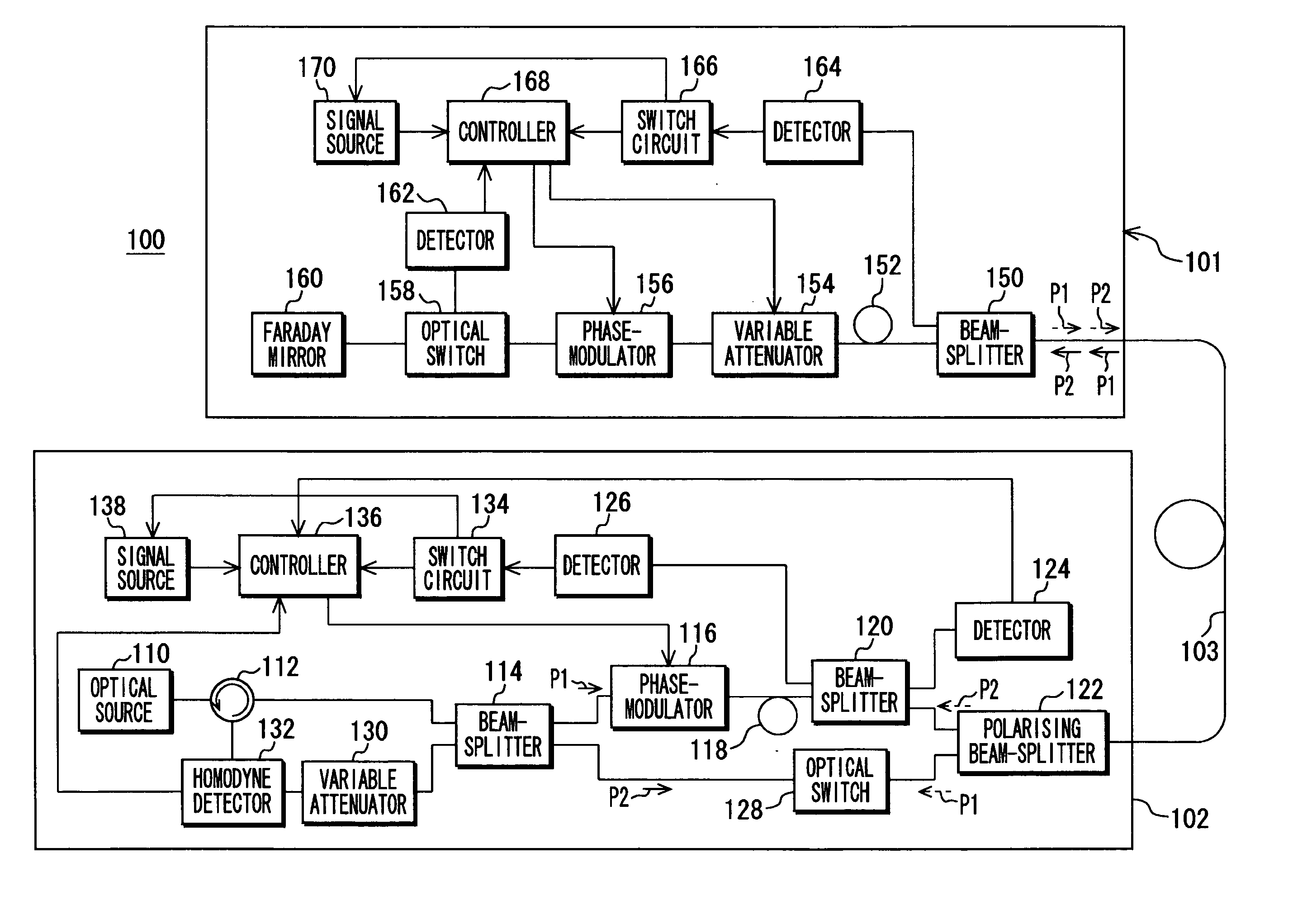
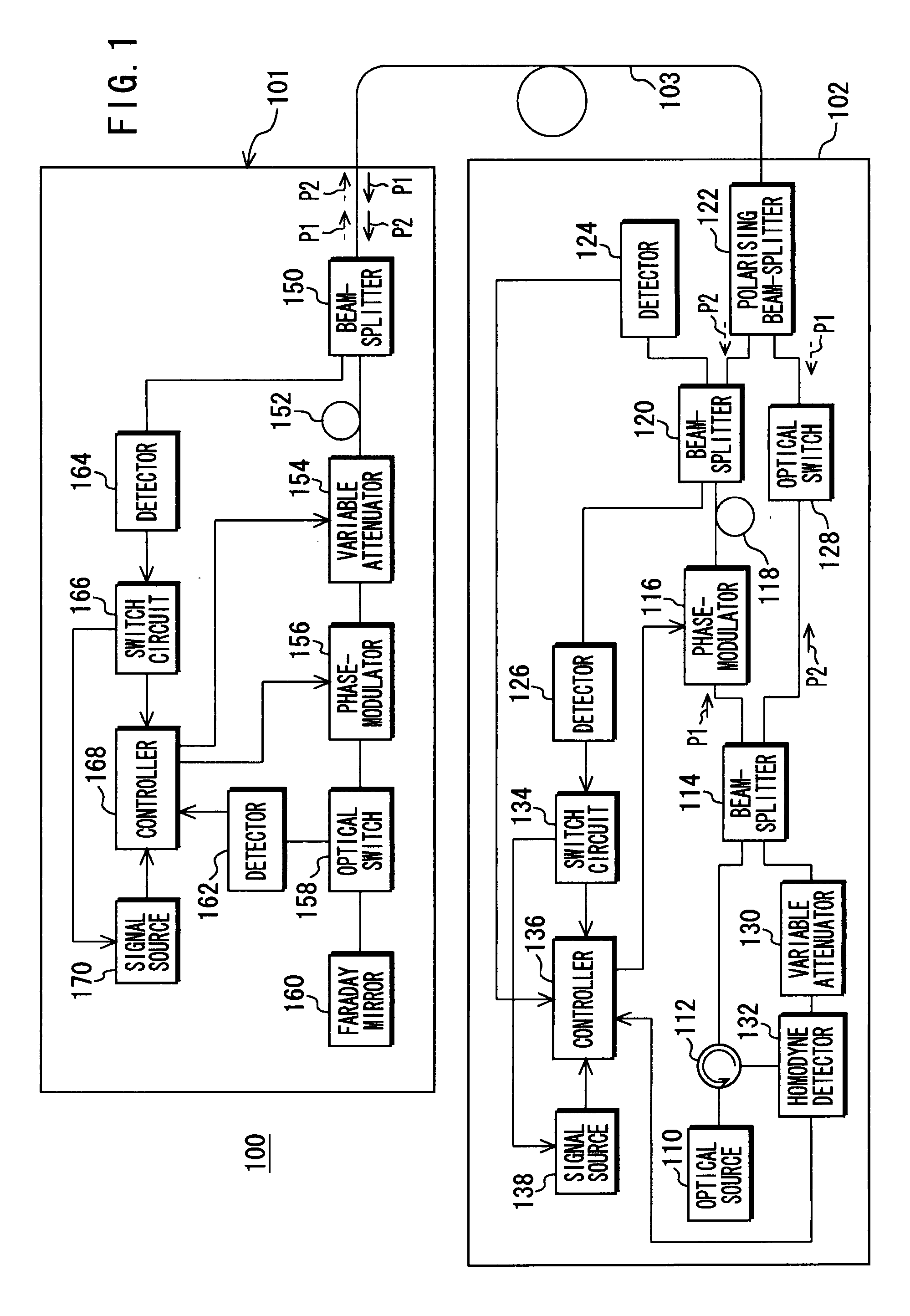
[0040] The following will describe embodiments of the present invention with reference to the drawings. FIG. 1 shows a configuration of an embodiment of a quantum cipher communication system 100 according to the invention.

[0041] The quantum cipher communication system 100 has a terminal 101 on a sender side (hereinafter referred to as “sender 101”) as a first communication terminal, a terminal 102 on a receiver side (hereinafter referred to as “receiver 102”) as a second communication terminal, and a communication path 103 that connects the sender 101 and the receiver 102. In quantum cipher communication system 100, the sender 101 sends any secret information toward the receiver 102 through the communication path 103. The secret information includes shared common key used in the common key cryptosystem.

[0042] The receiver 102 has an optical source 110, a circulator 112, a beam-splitter 114 having a 1:1 split ratio, a phase-modulator 116, delaying device 118, a beam-splitter 120, a...


PUM


Abstract

A quantum cipher communication system performs communication processing based on quantum cipher. It may have a first communication terminal, a second communication terminal, and a communication path that connects them. The first communication terminal may contain an optical source, a first light-separating device, optical paths, a light-synthesizing device, a second light-separating device, a first phase-modulator, and a homodyne detector that performs homodyne detection based on the reference light separated in the second light-separating device and passed through the first optical path and the signal light separated in the second light-separating device and passed through the second optical path. The second communication terminal may contain a light-sending device, an optical attenuator, a second phase-modulator, and a photon-number-setting device that sets to a predetermined value an average photon number of the signal light sent to the communication path from the light-sending device.

Description

CROSS-REFERENCE TO RELATED APPLICATIONS [0001] This application claims priority from Japanese Patent Application No. JP 2006-073449 filed in the Japanese Patent Office on Mar. 16, 2006, the entire content of which is incorporated herein by reference. BACKGROUND OF THE INVENTION [0002] 1. Field of the Invention [0003] The present invention relates to a quantum cipher communication system that performs communication processing based on quantum cipher and a method of setting an average photon number at a communication terminal, which is used in the quantum cipher communication system. [0004] 2. Description of Related Art [0005] Public key cryptosystems including an RAS cipher and an EL Gamal cipher and common key cryptosystem including an advanced encryption standard (AES) cipher and a data encryption standard (DES) cipher are in common use for preventing any information from being leaked to a third party. In the public key cryptosystems, their security is secured based on a difficulty...

Claims


Application Information

Patent Timeline
IPC IPC(8): H04K1/00H04B10/00H04B10/524H04B10/556H04B10/70H04L9/12
CPCH04L9/0858H04B10/70
Inventor KAWAMOTO, YOHEIHIRANO, TAKUYASHINO, KUNINORIUKITA, MASAKAZU
Owner SONY CORP
Learn More