Atomic force microscopy scanning and image processing

a scanning and image processing technology, applied in the field of scanning probe microscopy, can solve the problems of reducing the scan speed, affecting the measurement throughput, and affecting the relative size and position of features within the structure, and achieve the effect of correcting skew and til

Inactive Publication Date: 2007-11-01
SEAGATE TECH LLC
View PDF11 Cites 22 Cited by
  • Summary
  • Abstract
  • Description
  • Claims
  • Application Information

AI Technical Summary

Benefits of technology

[0005] The present invention relates to the generation of a topographic profile of a structure using atomic force microscopy. The structure is scanned such that an area of interest of the structure is scanned at a higher resolution than portions of the structure outside of the area of interest. An image of the structure is then generated based on the scan. To correct skew and tilt of the image, a first feature of the image is aligned with a first axis of a coordinate system. The image is then manipulated to align a second feature of the image with a second axis of the coordinate system. In one aspect, curvature artifacts are then removed from the image.

Problems solved by technology

However, a reduction in the size of the scan area removes contextual details around the scanned area of interest, which makes determining the relative sizes and positions of features within the structure difficult.
On the other hand, to increase in the amount of data in the scan, the scan speed may be reduced, which decreases measurement throughput and may result in drift errors in the image.
The increased amount of data in the scan also wastes the limited available data on areas outside of the areas of interest in the scan.
In addition, the small dimensions of the scanned structure result in missed details or the introduction of artifacts into the resulting image.
For example, when scanning a structure including features having significant topographical transitions, feedback overshoot may occur at the transition locations, resulting in lost details in the representative image at the transition locations.
In addition, a scan of a flat or planar feature in the structure may result in a curving or bowing artifact in the resulting image at the location of the flat or planar feature.
Image curvature may also occur when the scanning probe tip moves faster in one direction than the other along the structure surface because environmental vibrations, thermal drifting, and air flow along the probe tip may affect the image in the slower scan direction.

Method used


Image

  • Atomic force microscopy scanning and image processing
  • Atomic force microscopy scanning and image processing
  • Atomic force microscopy scanning and image processing

Examples


Embodiment Construction

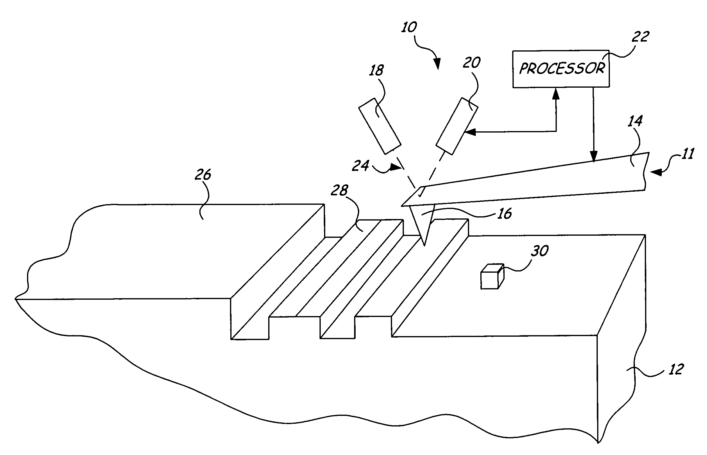
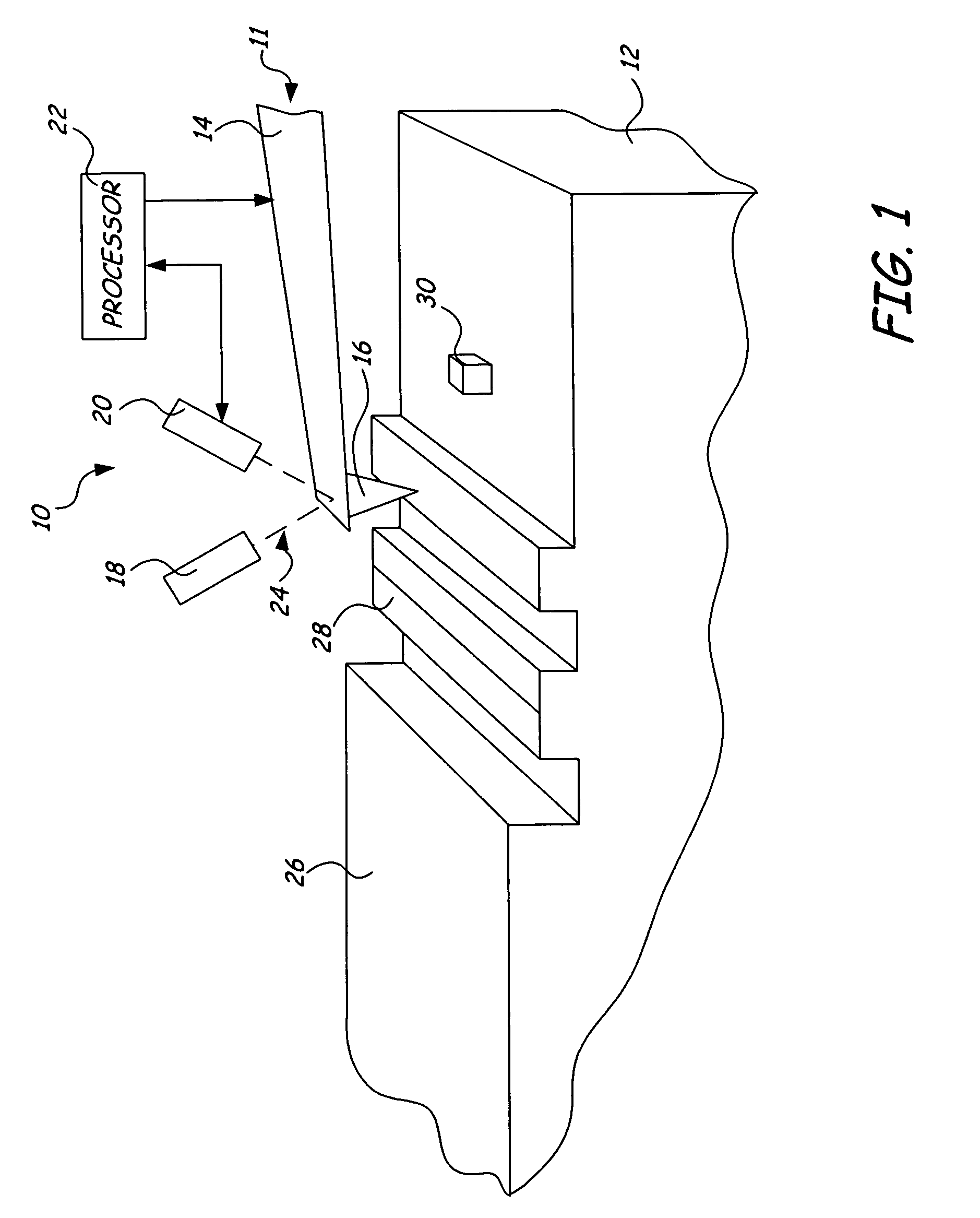
[0018]FIG. 1 is a perspective view an atomic force microscope 10 positioned over a surface of structure 12. Atomic force microscope 10 includes probe 11 having cantilever portion 14 and tip portion 16. Atomic force microscope 10 also includes light source 18, position sensitive detector 20, and processor 22. Light source 18 emits a beam 24 that is reflected by cantilever 14 and received by position sensitive detector 20. Processor 22 receives signals from position sensitive detector 20 and provides signals to control movement of probe 11 relative to structure 12.

[0019] Structure 12 is the pole tip region of a magnetic recording system, including slider 26 carrying reader structure 28 and writer structure 30. The atomic force microscopy (AFM) techniques described herein are useful for measuring and imaging feature characteristics of structure 12, such as pole tip recession (PTR) features of reader structure 28 and writer structure 30. It should be noted that structure 12 is shown me...


PUM


Abstract

A topographic profile of a structure is generated using atomic force microscopy. The structure is scanned such that an area of interest of the structure is scanned at a higher resolution than portions of the structure outside of the area of interest. An profile of the structure is then generated based on the scan. To correct skew and tilt of the profile, a first feature of the profile is aligned with a first axis of a coordinate system. The profile is then manipulated to align a second feature of the profile with a second axis of the coordinate system.

Description

BACKGROUND OF THE INVENTION [0001] The present invention relates to scanning probe microscopy, and more particularly to using atomic force microscopy to produce an image profile representative of a structure. [0002] Atomic force microscopy (AFM) is a metrology technique that is useful for measuring and imaging surface features of structures having dimensions in the nanometer and micrometer range. AFM may be used to scan structures made of any material in a short period of time to produce high resolution two-dimensional and three-dimensional images of the structure. AFM is an important tool for measuring dimensions of devices in the semiconductor industry, including magnetic recording devices and microelectromechanical system (MEMS) devices. [0003] The lateral resolution of an image produced from an AFM scan of a structure is defined by the scan area size and the number of pixels in the image. Thus, in order to increase the lateral resolution of an image, the size of the scan area ma...

Claims


Application Information

Patent Timeline
Patent Type & Authority Applications(United States)
IPC IPC(8): G01B5/28
CPCB82Y35/00G01Q40/00G01Q30/06
Inventor ZHOU, LINLIU, HUIWENEGBERT, DALENELSON, JONATHAN A.ZHU, JIANXIN
Owner SEAGATE TECH LLC
Why Eureka
Try Eureka