Bearing Lubricating Device

a lubricating device and bearing technology, applied in the direction of crankshafts, mechanical devices, engine components, etc., can solve the problems of increasing the manufacturing cost of the conventional lubricating device, the assembly process for fixing the lubricating device to the bearing is complicated, etc., to reduce the size of the lubricating member, reduce the amount of lubricant, and reduce the effect of manufacturing cos

Active Publication Date: 2007-11-01
NIPPON THOMPSON
View PDF2 Cites 6 Cited by
  • Summary
  • Abstract
  • Description
  • Claims
  • Application Information

AI Technical Summary

Benefits of technology

[0017]According to the present invention, when the casing is fitted around the outer ring, the lubricating member is designed to be in contact with the outer ring either on a center line, that extends in parallel to a tangent passing through a contact point between the outer ring and a supported item borne on the outer ring and passes through the center of the outer ring, or on the opposite side of the line to the contact point. In consequence, a reduction in size of the lubricating member is possible.
[0018]Even if the lubricating member is reduced in size, the lubricating member can hold sufficient lubricant to match the service life of the bearing or a machine equipped with the bearing. As a result, the size reduction of the lubricating member enables a reduction in manufacturing costs.
[0019]Further, according to the present invention, the lubricating member is designed to be disposed in an area on the opposite side, to the contact point, of the center line extending through the center of the outer ring and parallel to the tangent passing through the contact point between the outer ring and the supported item borne on the outer ring, and also in a sector which is symmetrical with respect to a center line passing through the center of the outer ring and the contact point, and ranges within an angle of 60 degrees on each side from the center line. As a consequence, a further reduction in an unnecessary amount of lubricant is possible.
[0020]In turn, the reduction in the unnecessary amount of lubricant enables a further reduction in the manufacturing costs of the lubricating device.
[0021]Still further, according to present invention, an elastic member is interposed between the casing and the lubricating member and pressing the lubricating member against the outer ring after the casing has been fitted over the outer periphery of the outer ring. In consequence, the dimensional control of the lubricating member can be somewhat eased. Also, the provision of the elastic member eliminates the need to exercise great care in adjusting the degree of contact between the outer ring and the lubricating member in the assembly process of fitting the bearing into the lubricating device, resulting in simplification of the assembly process.

Problems solved by technology

In this way, the manufacturing costs for the conventional lubricating device 4 increase because the lubricating member 6 contains a greater amount of lubricant than necessary.
Also, a complicated assembly process for fixing the lubricating device to the bearing is necessary.

Method used


Image

  • Bearing Lubricating Device
  • Bearing Lubricating Device
  • Bearing Lubricating Device

Examples


first embodiment

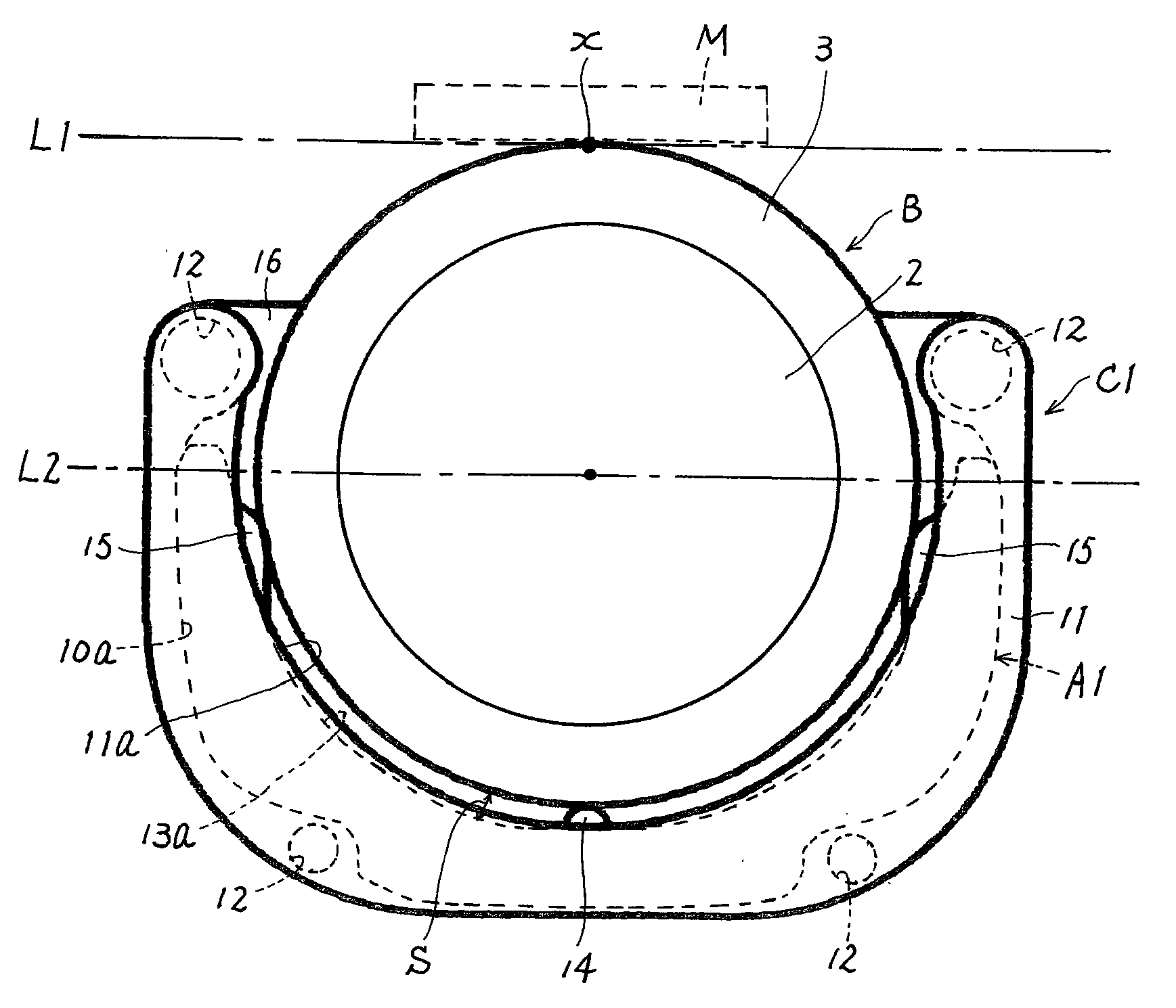
[0042]In the lubricating device because the lubricating member A1 and the outer ring 3 are in contact with each other below the center line L2, the need for the lubricating member A1 to extend above the center line L2 is eliminated, thus reducing the size of the lubricating member A1.

[0043]Even if the lubricating member A1 is reduced in size, the lubricating member A1 can hold sufficient lubricant to match the service life of the bearing B. As a result, the size reduction of the lubricating member A1 enables a reduction in manufacturing costs without affecting the lubrication of the outer ring 3.

[0044]In addition, because a clearance S is created between the outer ring 3 and the lubricating member A1, dust and the like involved with the rotation of the outer ring 3 can be collected in the clearance S.

second embodiment

[0045]Next, FIGS. 4A and 4B illustrate the present invention, which will be described below.

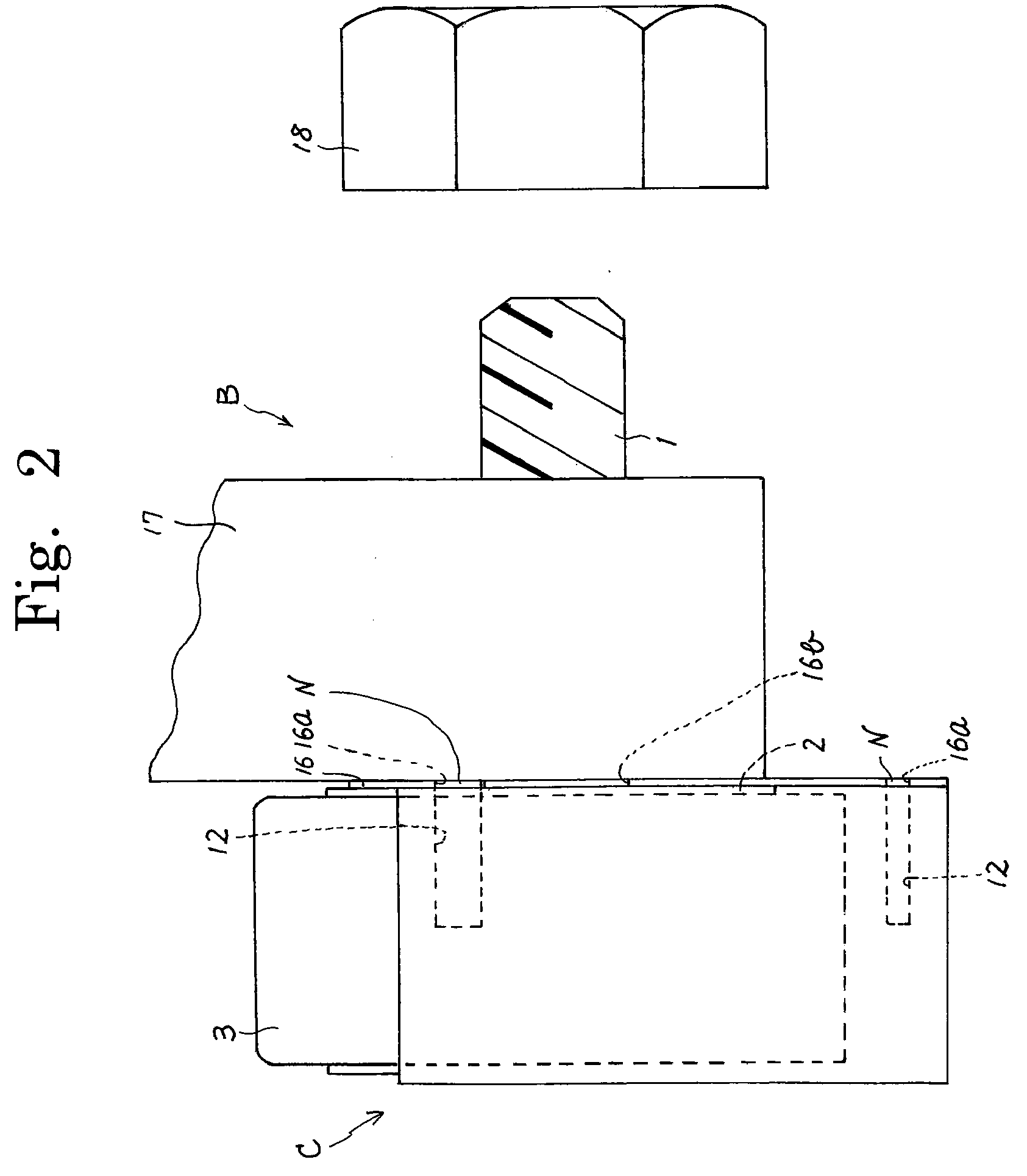
[0046]The lubricating device according to the second embodiment differs from the lubricating device of the first embodiment in the shape of the lubricating member and the shape of the casing, but is identical in the structure and the operation of the main body 10, side portion 11, recess 11a, screw holes 12, lubricant protrusion portions 14, 15, plate member 16, screw holes 16a support-shaft hole 16b, fixing member 17 and the nut 18. Therefore, the same structural components in the second embodiment as those in the first embodiment are designated with the same reference numerals. The second embodiment will be described with emphasis on the differences from the first embodiment. Note that the side view of FIG. 2 described in the first embodiment holds good for the second embodiment.

[0047]The lubricating device comprises, as illustrated in FIG. 4A, a casing C2, a lubricating member A2 fitted in...

third embodiment

[0059]Next, the present invention will be described with reference to FIG. 5A and FIG. 5B.

[0060]The lubricating device according to the third embodiment differs from the lubricating device of the second embodiment in that an elastic member, as described below, is provided, but is identical in the structure and the operation of the other components. Therefore, the same structural components in the third embodiment as those in the second embodiment are designated with the same reference numerals. The third embodiment will be described with emphasis on the differences from the second embodiment.

[0061]As shown in FIGS. 5A and 5B, in the lubricating device, when the lubricating member A2 is fitted into the recess 19 of the casing C2, an elastic member 21 in the form of a leaf spring is interposed between the bottom of the casing C2 and the lubricating member A2.

[0062]Accordingly, once the lubricating device is fixed to the bearing B, the lubricating member A2 is pressed against the outer...


PUM


Abstract

A bearing lubricating device, reducing the manufacturing cost and facilitating the dimensional control and the assembly process, comprises a casing provided around an outer ring rotating relatively to a support shaft; and a lubricating member provided in the casing, which is, after the casing has been fitted over the outer periphery of the outer ring, in contact with the outer ring to apply a lubricant contained in the lubricating member to the outer periphery of the outer ring. When the casing is fitted around the outer ring, the lubricating member is in contact with the outer ring in a position either on a line, that extends in parallel to a tangent passing through a contact point between the outer ring and a supported item borne on the outer ring and passes through the center of the outer ring, or on the opposite side of the line to the contact point.

Description

FIELD OF THE INVENTION[0001]This invention relates to a bearing lubricating device for lubricating an outer ring of a bearing.BACKGROUND OF THE INVENTION[0002]One of the conventional lubricating devices for lubricating an outer ring of the bearing is disclosed in Japanese Unexamined Patent Publication 2004-270876, for example. The conventional lubricating device will be described with reference to FIG. 6.[0003]This conventional lubricating device is fixed to a bearing B. The bearing B comprises a support shaft 1, an inner ring 2 having a diameter greater than that of the support shaft 1 and receiving the support shaft 1 inserted therein, and an outer ring 3 provided around the inner ring 2. A plurality of rollers are rotatably interposed between the inner ring 2 and the outer ring 3 so as to allow for smooth relative rotation of the outer ring 3 to the support shaft 1 and inner ring 2.[0004]The bearing B structured as described above supports the supported item on the outer ring 3 s...

Claims


Application Information

Patent Timeline
Patent Type & Authority Applications(United States)
IPC IPC(8): F16N1/00
CPCF16C33/103F16C33/102
Inventor TSUBOI, TAKAAKIIDA, EIJI
Owner NIPPON THOMPSON
Why Eureka
Try Eureka