Hollow cathode magnetron sputtering targets and methods of forming hollow cathode magnetron sputtering targets

a technology of hollow cathode magnetron and hollow cathode magnetron, which is applied in the direction of vacuum evaporation coating, electrolysis components, coatings, etc., can solve the problems of difficult to fabricate monolithic targets having geometry similar, difficult to achieve pvd process success, and difficult to achieve conventional targets including conventional three-dimensional targets

Inactive Publication Date: 2007-11-01
HONEYWELL INT INC
View PDF57 Cites 31 Cited by
  • Summary
  • Abstract
  • Description
  • Claims
  • Application Information

AI Technical Summary

Benefits of technology

[0008] In one aspect, the invention encompasses a method of forming a hollow cathode magnetron sputtering target. A metallic material is processed to produce an average grain size of less than or equal to about 20 microns. The material is then subjected to deep drawing.
[0009] In one aspect the invention encompasses a three-dimensional sputtering target comprising a metallic material containing at least one element selected from Cu, Ti, and Ta. The target has an average grain size of from about 0.2 microns to about 30 microns throughout the target. The target has a gra

Problems solved by technology

Difficulties are encountered during PVD processes in attempting to obtain a uniform thickness across a semiconductor substrate surface, particularly where the substrate surface comprises various topological features and/or complex geometric features.
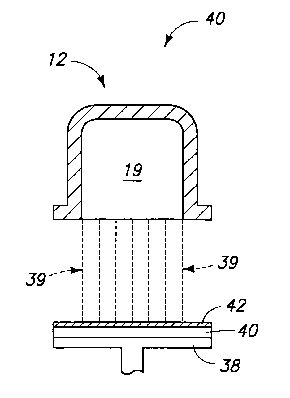
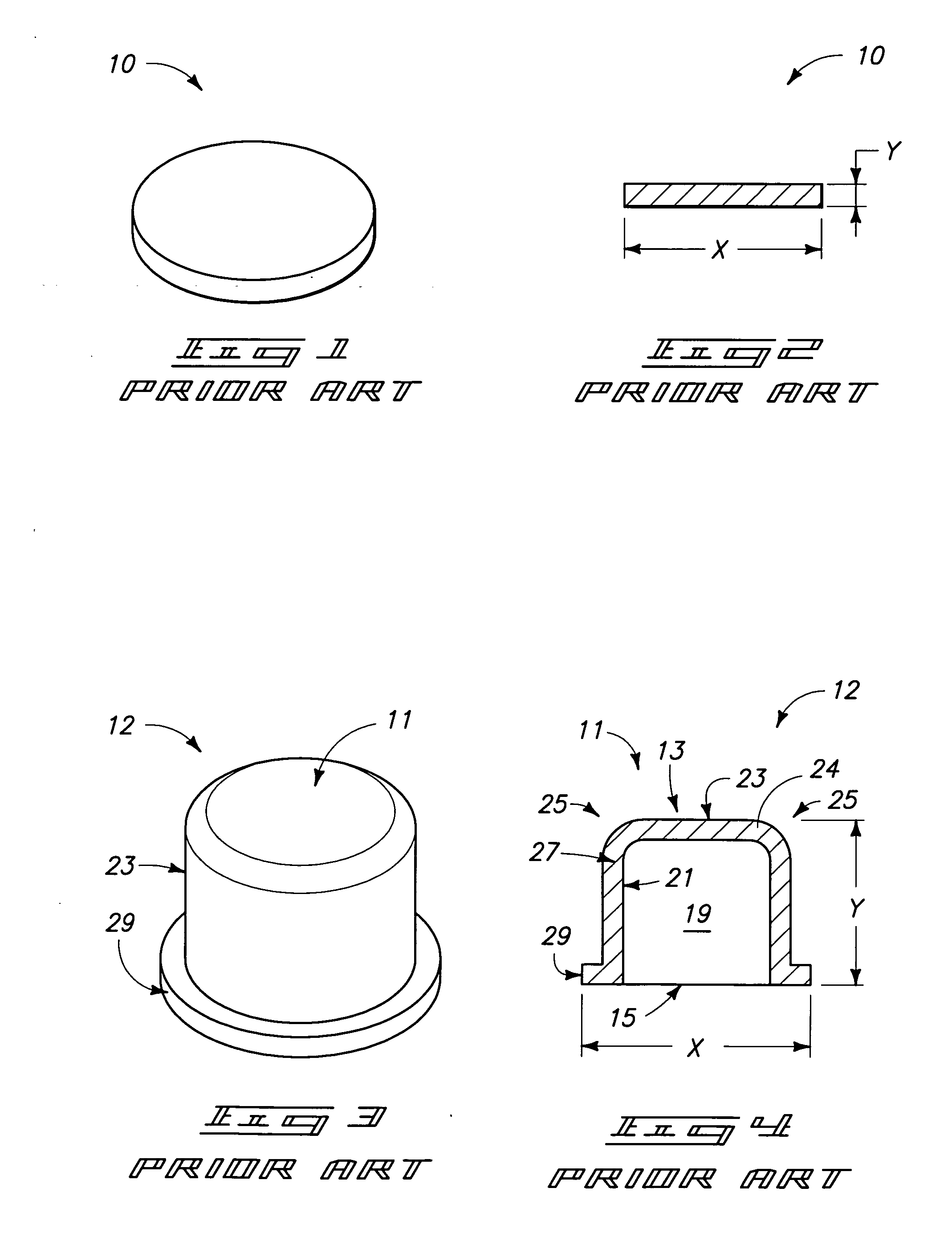
The exemplary target depicted in FIG. 4 can be considered to comprise a complex three-dimensional geometry in that it can

Method used


Image

  • Hollow cathode magnetron sputtering targets and methods of forming hollow cathode magnetron sputtering targets
  • Hollow cathode magnetron sputtering targets and methods of forming hollow cathode magnetron sputtering targets
  • Hollow cathode magnetron sputtering targets and methods of forming hollow cathode magnetron sputtering targets

Examples


examples

[0061] In one study, a composition comprising 6N copper (99.9999%, by weight) to which was added 1.7-1.9 ppm Ag was subjected to six passes of equal channel angular extrusion (route D) followed by 70% reduction by rolling, and annealing at 235° C. for 1 hour. The effects of deep drawing and annealing after deep drawing were investigated utilizing two independent pieces of the 10 micron ECAE silver-doped copper. A first piece had a diameter of from 8.5 inches, and a second piece had a diameter of about 9 inches. Each of the first and second pieces had a thickness of 0.375 inches prior to deep drawing.

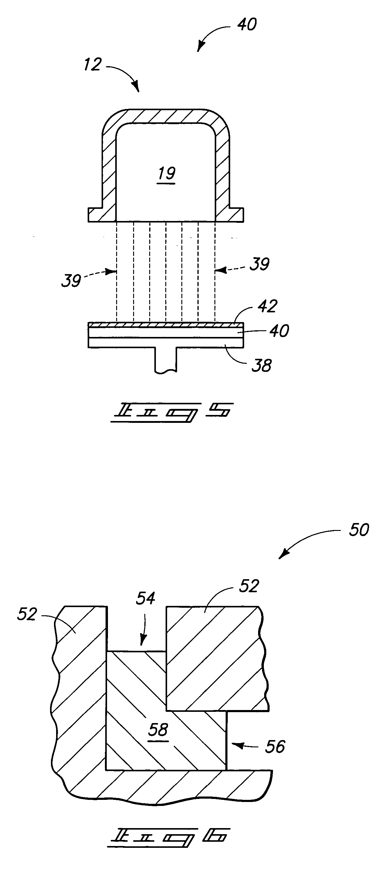
[0062] Referring to FIG. 7, such illustrates the cross-section of an exemplary deep drawn target 12A which illustrates a top portion 60, a side portion 62 which surrounds hollow interior 19, and a radius portion 64 (disposed at the intersection between side portion 62 and top portion 60). Each of the two deep drawn targets was sampled along the top, side and radius portions to observe e...


PUM

PropertyMeasurementUnit
Grain sizeaaaaaaaaaa

Abstract

The invention includes methods of forming hollow cathode magnetron sputtering targets. A metallic material is processed to produce an average grain size of less than or equal to about 30 microns and subsequently subjected to deep drawing. The invention includes three-dimensional sputtering targets comprising materials containing at least one element selected from Cu, Ti, and Ta. The target has an average grain size of from about 0.2 microns to about 30 microns throughout the target and a grain size standard deviation of less than or equal to 15% (1-σ). The invention includes three-dimensional targets comprising Al, having an average grain size of from 0.2 microns to less than 150 micron, with a grain size standard deviation of less than or equal to 15% (1-σ).

Description

TECHNICAL FIELD [0001] The invention pertains to three-dimensional physical vapor deposition (PVD) targets such as, for example, hollow cathode magnetron targets, and methods of forming three-dimensional PVD. BACKGROUND OF THE INVENTION [0002] Physical vapor deposition (PVD) is commonly used for forming thin layers of material in processes such as semiconductor fabrication. PVD includes sputtering processes. In an exemplary PVD process a cathodic target is exposed to a beam of high-intensity particles. As the high-intensity particles impact a surface of the target, they force materials to be ejected from the target surface. The materials can then deposit onto a semiconductor substrate to form a thin film of the materials across a substrate. [0003] Difficulties are encountered during PVD processes in attempting to obtain a uniform thickness across a semiconductor substrate surface, particularly where the substrate surface comprises various topological features and / or complex geometri...

Claims


Application Information

Patent Timeline
IPC IPC(8): C23C14/00
CPCC23C14/3414C23C14/34C23C14/35
Inventor KARDOKUS, JANINE K.STROTHERS, SUSAN D.WOODWARD, SALLY A.FERRASSE, STEPHANE
Owner HONEYWELL INT INC
Why Eureka
Try Eureka