Probe for Measuring Characteristics of an Excitation Current of a Plasma, and Associated Plasma Reactor

a technology of excitation current and probe, which is applied in the field of probe for measuring characteristics of excitation current of plasma, and associated plasma reactor, can solve the problems of large error in phase offset measurement between current and voltage, and the inability of most existing probes designed to work at 13.56 mhz to be used at vhf,

Inactive Publication Date: 2007-11-01
ECOLE POLYTECHNIQUE +1
View PDF6 Cites 30 Cited by
  • Summary
  • Abstract
  • Description
  • Claims
  • Application Information

AI Technical Summary

Problems solved by technology

Most of the existing probes designed to work at 13.56 MHz are therefore not usable at VHF.
It is observed with known voltage and current probes that the phase offset measured between the current and the voltage is affected by an error (this error generally becoming greater as the current and voltage sensors of the probe are more distant from each other).
The solution, which would consist of bringing to the same level the current and voltage sensors of a probe of previous design (such as that shown in FIG. 2) in order to attempt to get around this type of error, would also increase the risk of mutual interference and would result in a degradation of the frequency response.
However, a voltage measured between these two cables has certain limitations:
firstly, the response of such a voltage probe is restricted in frequency,
finally the line 20 is partially short-circuited by the conductor 110, which can cause material breakdown, thus restricting the measurable voltage range.
This constitutes an additional voltage component which renders the measurement of the current less precise, and also disrupts the measurement of the phase offset between the current and the voltage.
In practice, the use of such a loop is therefore generally limited to powers below 10 kW.
Moreover, because of the large size of the loop, it is also difficult to place a voltage sensor V2 close by without the current and voltage sensors disrupting each other.
It is then necessary to move these two sensors away from each other—which then introduces an error into measurement of the phase offset between the current and the voltage.
Thus existing probes seeking to measure, in real time, the current and the voltage delivered by an RF generator to a plasma have various limitations.

Method used


Image

  • Probe for Measuring Characteristics of an Excitation Current of a Plasma, and Associated Plasma Reactor
  • Probe for Measuring Characteristics of an Excitation Current of a Plasma, and Associated Plasma Reactor
  • Probe for Measuring Characteristics of an Excitation Current of a Plasma, and Associated Plasma Reactor

Examples


Embodiment Construction

[0125]FIG. 3 schematically represents a probe according to one embodiment of the invention.

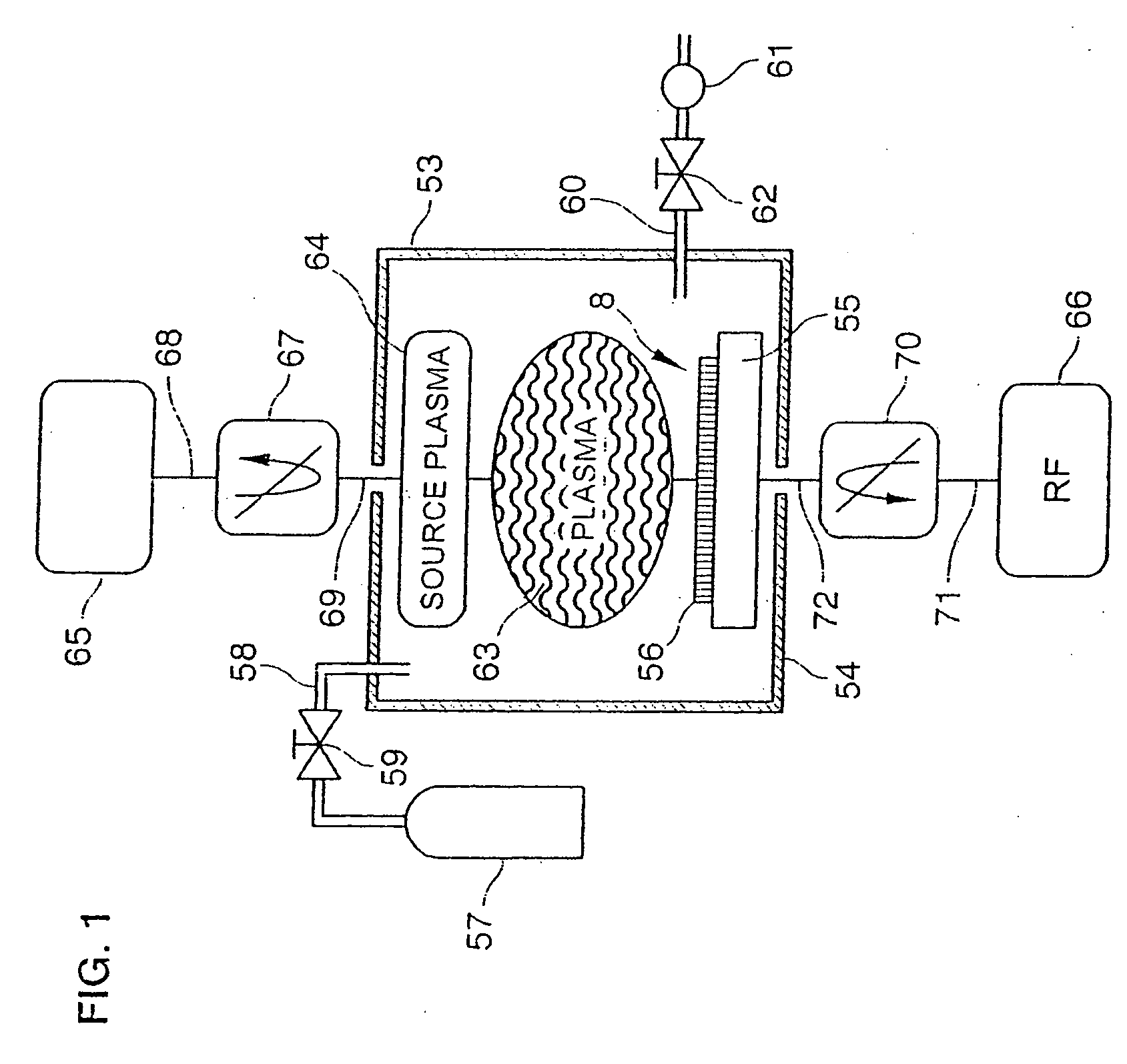
[0126] The probe is mounted between an RF electrode and an impedance matching circuit connected to an RF generator (not shown).

[0127] As has been described above, an impedance matching circuit can be used in plasma processes in particular in order to optimize the transfer to the plasma of the power delivered by the RF generator.

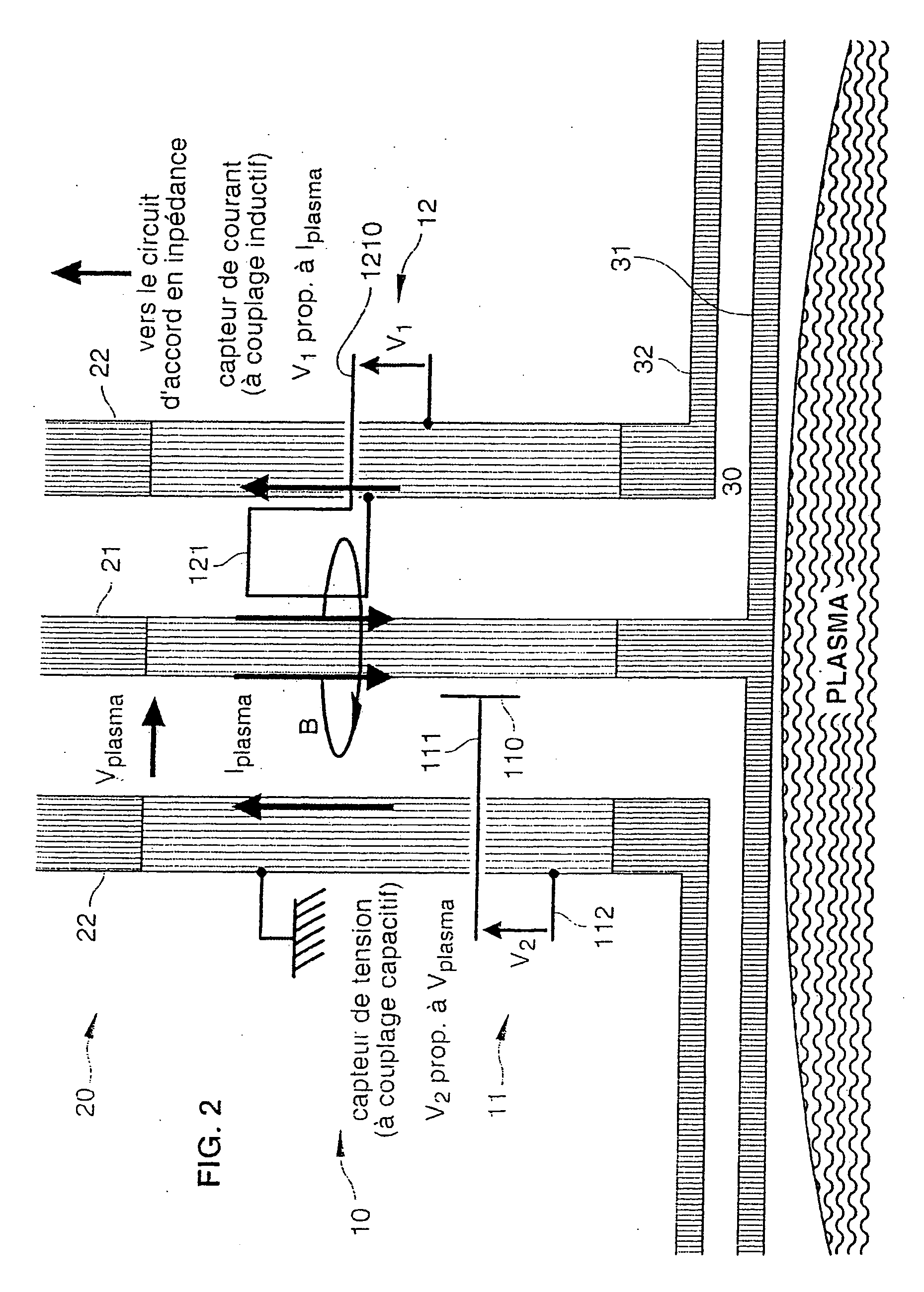
[0128] Note that the elements already mentioned in relation to the known probe shown in FIG. 2 will be referenced in the same way with reference to FIG. 3 (without being newly introduced).

[0129] This figure thus includes:

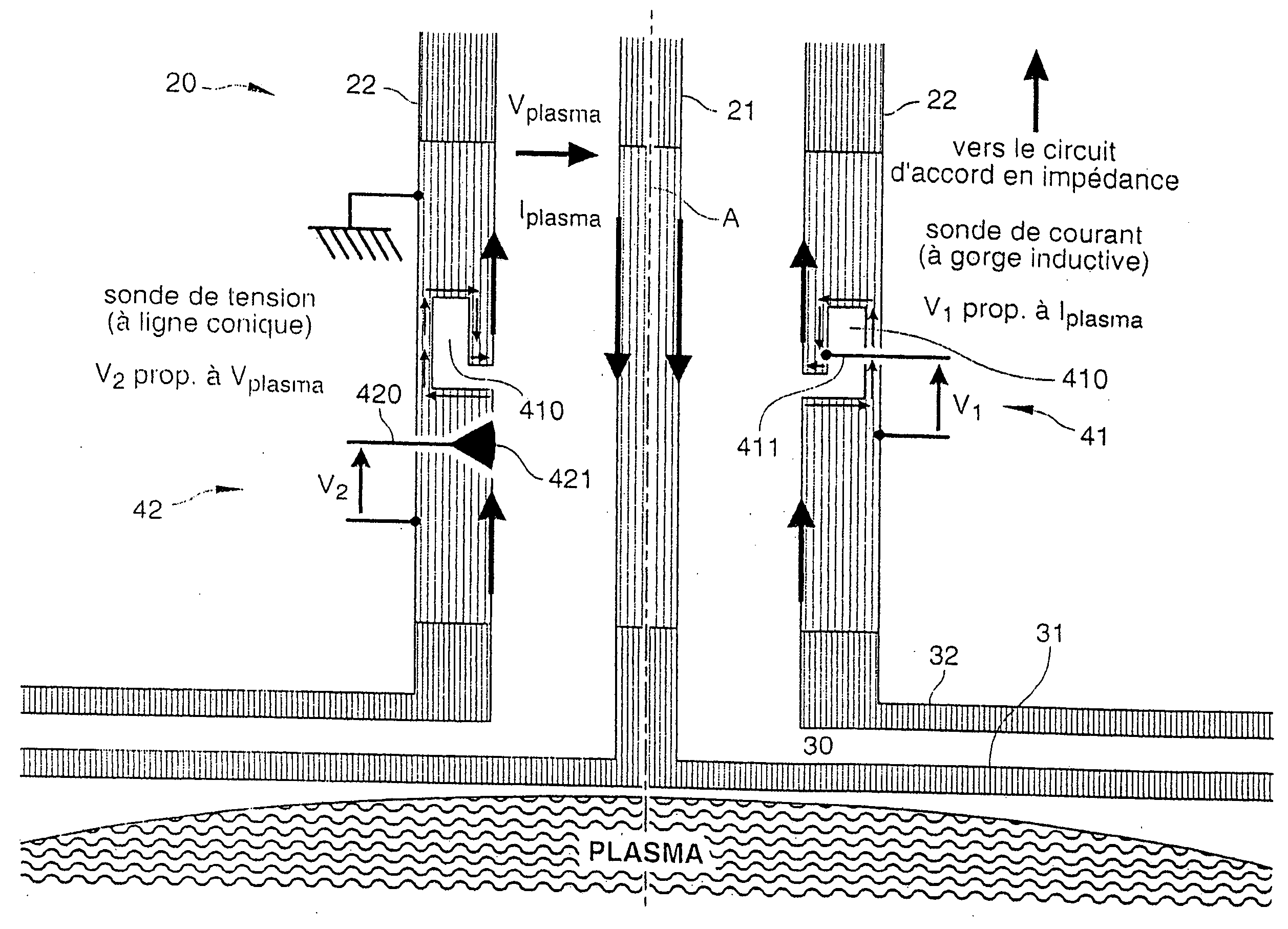
[0130] a conducting coaxial transmission line 20 which includes an inner conductor 21 and an outer conductor 22, and

[0131] an RF electrode 31 in form of disk, and an associated lid 32.

[0132] Note however that the probe according to the invention can be mounted differently, as described further below.

[0133] There is also a current sensor (here 41...


PUM


Abstract

A probe for measuring electrical characteristics of an excitation current of a plasma is provided. The probe is mounted on a conductive line that includes an inner conductor and an outer conductor. The probe includes a current sensor and a voltage sensor. The current sensor includes a grove formed in the ground of one of the conductors in order to form a detour for the current flowing through the conductor, and a point for measuring electric voltage between a ground connected to the conductor and a point of the groove. The current sensor thus is able to measure a voltage proportional to the first time derivative of intensity (Iplasma) of the excitation current. The voltage sensor is a shunt sensor capable of measuring a voltage proportional to the first time derivative of the voltage (Vplasma) of the excitation current. A plasma reactor including a probe of the aforementioned type is also provided.

Description

BACKGROUND OF THE INVENTION [0001] 1. Field of the Invention [0002] The invention relates to a device for measuring electric current and voltage in a power feeding circuit of a plasma. In this document, such a device will be referred to as a “probe”. [0003] 2. Discussion of Related Art [0004] The uses of the invention relate to all of the plasma-assisted industrial processes employed within a plasma reactor. In particular, such processes include (though this list is not exhaustive): [0005] plasma etching (used in particular in microelectronics or in the nanotechnology area), [0006] deposition of layers assisted by plasma (used, for example, for the manufacture of flat liquid crystal screens, etc.), and [0007] applications for which the plasma is used as a light source or as a device for the treatment of gaseous effluents in pollution control applications or even as a thermonuclear fusion reactor, etc. [0008] The invention also applies to measurement of the electric current and the v...

Claims


Application Information

Patent Timeline
Patent Type & Authority Applications(United States)
IPC IPC(8): G01R1/06G01R19/00H05H1/00
CPCH05H1/0081
Inventor DINE, SEBASTIENJOLLY, JACQUESLAROUR, JEAN BERNARD PIERRE
Owner ECOLE POLYTECHNIQUE
Why Eureka
Try Eureka