Radio frequency identification (RFID) portal antenna mounting frame

Inactive Publication Date: 2007-11-01
JAMISON DOOR
View PDF11 Cites 29 Cited by
  • Summary
  • Abstract
  • Description
  • Claims
  • Application Information

AI Technical Summary

Benefits of technology

[0008] The invention overcomes the above-noted and other deficiencies of the prior art by providing a mounting structure for a radio frequency identification (RFID) system having at least one antenna and a transceiver controller unit and includes an enclosed mounting pole and a bracket that has a hand-tightened fastener that grips the po

Problems solved by technology

In addition, the open framework exposes the RFID antennas and associated equipment to the environment where they are more prone to being damaged.
However, the enclosure tends to limit the flexibility of the placement of the antennas to the detriment of needed reception for some applications.
In many cases this in inconvenient and time consuming and in some cases the antenna can be dropped o

Method used


Image

  • Radio frequency identification (RFID) portal antenna mounting frame
  • Radio frequency identification (RFID) portal antenna mounting frame
  • Radio frequency identification (RFID) portal antenna mounting frame

Examples


Embodiment Construction

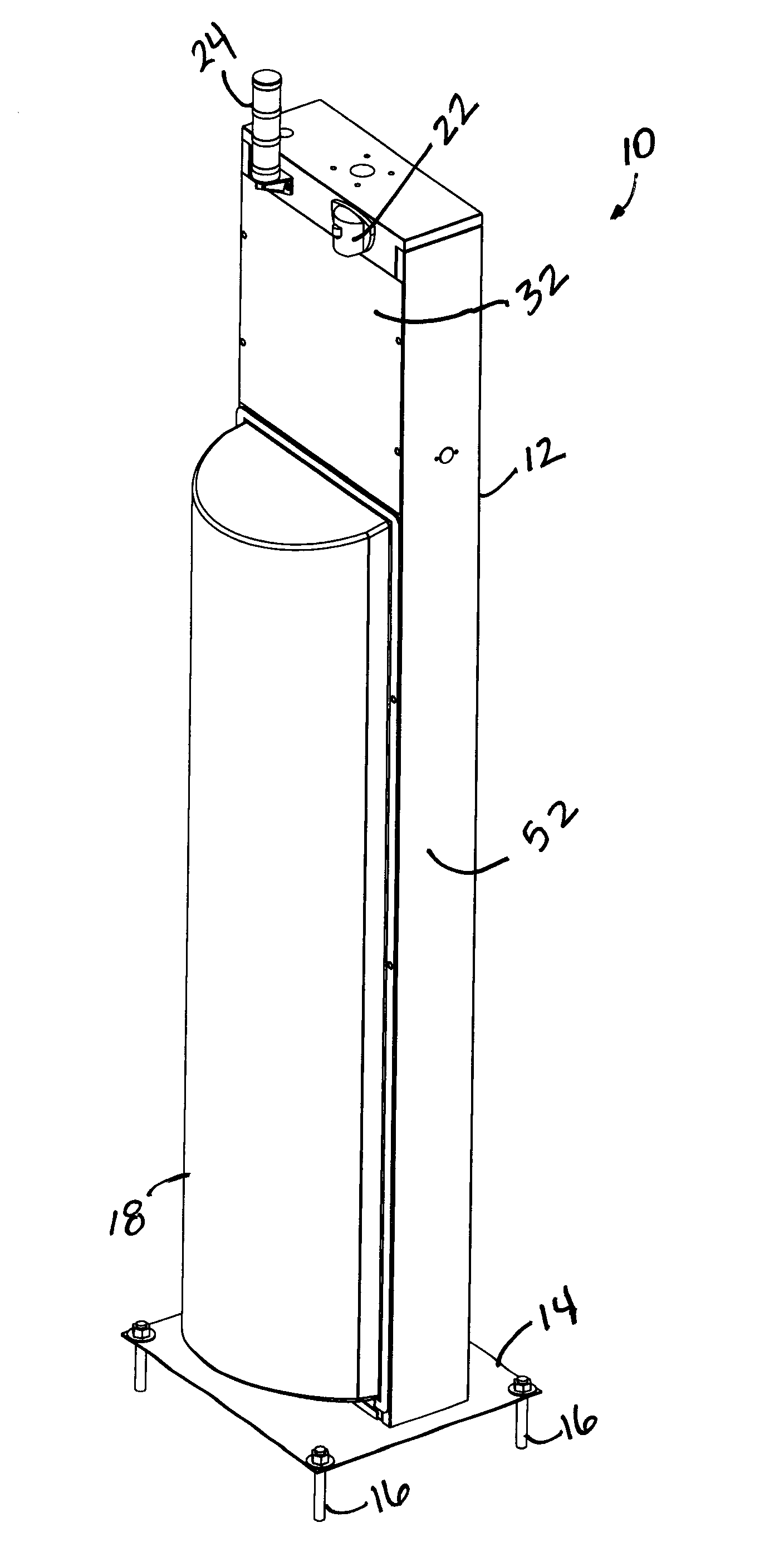
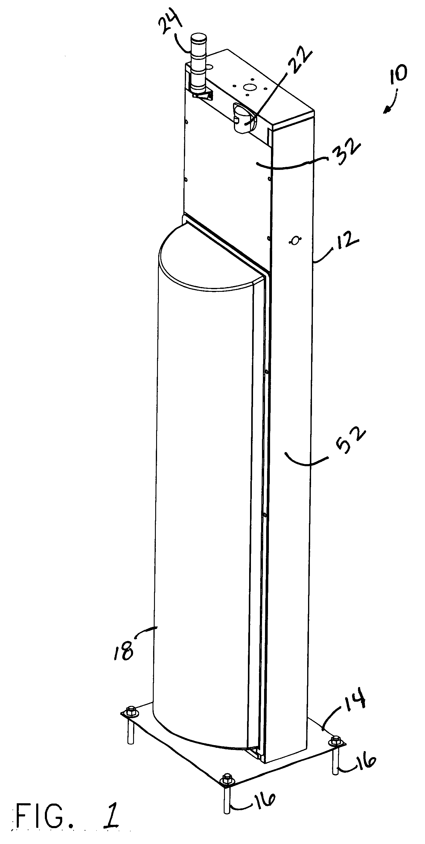
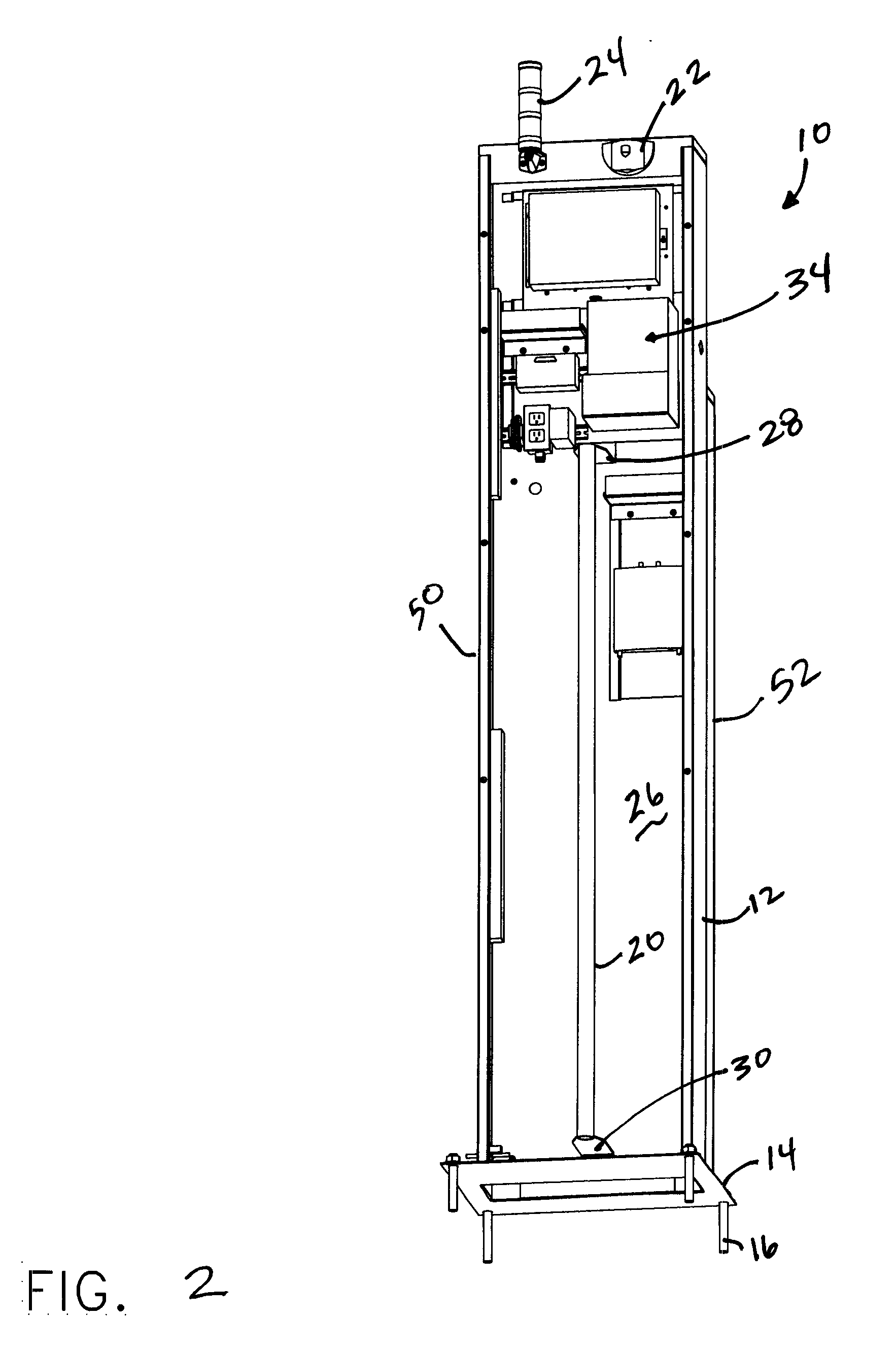
[0024] Turning to the Figures, wherein like numerals denote like components throughout the several views, in FIGS. 1-2, a first version of a Radio Frequency Identification (RFID) reader station 10 comprises a stand-alone pedestal cabinet 12 atop a floor plate 14 having fasteners 16 intended for permanent installation into flooring or substrate (e.g., concrete) adjacent to a traffic pathway (e.g., a doorway). A longitudinally bisected elongate half-cylindrical radome 18 encloses a vertical mounting pole 20 (FIG. 2).

[0025] A motion detector 22 and a light stack 24 may be attached to the RFID reader station 10 for providing guidance to personnel such as forklift operators and / or to indicate operating status. Audible signals may be provided in addition to or as an alternative to visual signals. For example, a red light provided by the light stack 24 may indicate that one or more RFID tags cannot be successfully read, although the motion detector 22 indicates that an object presumed to ...


PUM


Abstract

A radio frequency identification (RFID) portal easily installs and integrates any RFID hardware/software systems. The RFID portal may match the size of a traditional dock or be custom sized. The portal takes advantage of a variety of unique features including an antenna bracket that provides for three-dimensional vertical and horizontal movements and a hardware independent reader bracket. The antenna movement capabilities allow for excellent RFID signal coverage. A General Purpose Input/Output (GPIO) bridge enables rapid integration and functionality to other RFID inputs such as Motion Detectors/Photo Eyes, Uninterrupted Power Supply (UPS), Wireless Networking, floor loops, mass detectors, and output signals, such as to light stacks and RFID readers.

Description

CROSS REFERENCE TO RELATED APPLICATIONS [0001] The present application claims the benefit of U.S. pat. appln. Ser. No. 60 / 795,940 “Radio Frequency Identification (RFID) Portal Antenna Mounting Frame” To Berry et al., filed 28 Apr. 2006, the disclosure of which is hereby incorporated by reference in its entirety.FIELD OF THE INVENTION [0002] The present invention relates, in general, to radio frequency identification (RFID) systems, and more particularly to mounting structures for RFIU) system antennas and transceivers. BACKGROUND OF THE INVENTION [0003] One aspect of installing a radio frequency identification (RFID) system is antenna mounting and direction sensing. Typically RFID antennas are mounted on an open framework and are gimbaled to positions that provide the best reception. Relocating the antenna racket on the open framework and realigning the antenna is the generally known way to adjust the position of the antenna pattern. In addition, the open framework exposes the RFID ...

Claims


Application Information

Patent Timeline
IPC IPC(8): G08B13/14H01Q1/12
CPCG06K7/10336H01Q1/088H01Q1/42H01Q1/2216H01Q1/1207
Inventor BERRY, CURTIS L.WARREN, MARK TIMOTHY JR.
Owner JAMISON DOOR
Why Eureka
Try Eureka