Method and apparatus for recording of images and study of surfaces

a surface and image technology, applied in the field of recording images, can solve the problems of low analysis power, loss of detector phase, and loss of electric field in the detector, and achieve the effect of reducing the power of analysis

Inactive Publication Date: 2007-11-01
MICRONIC LASER SYST AB
View PDF20 Cites 33 Cited by
  • Summary
  • Abstract
  • Description
  • Claims
  • Application Information

AI Technical Summary

Problems solved by technology

However, the electric field also has a phase that is lost in the detector.
Thus, when only intensity is recorded, we have very little knowledge about the actual electric field in the image.
Because only intensity information is recorded, the power of analysis is limited.
This is the subject of so-called inverse imaging problems, where one or several images are combined with a priori knowledge to analyze surface characteristics beyond what the image alone shows.

Method used


Image

  • Method and apparatus for recording of images and study of surfaces
  • Method and apparatus for recording of images and study of surfaces
  • Method and apparatus for recording of images and study of surfaces

Examples


embodiments 1-8

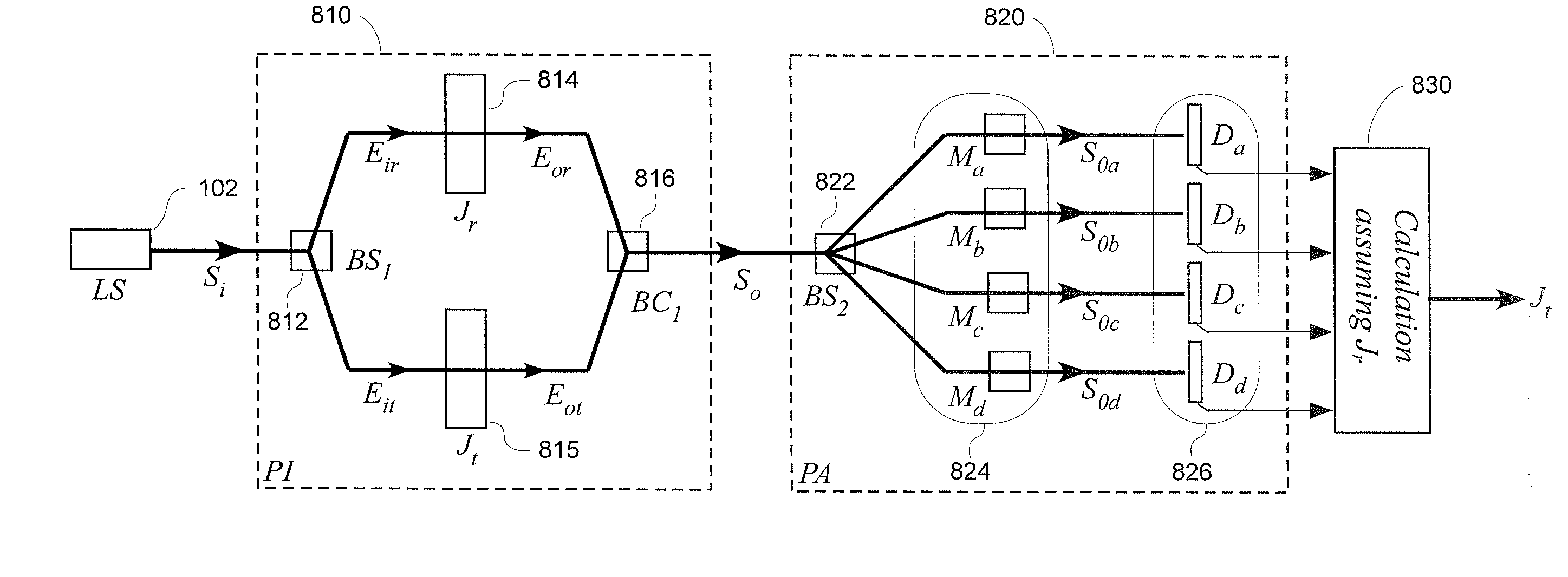
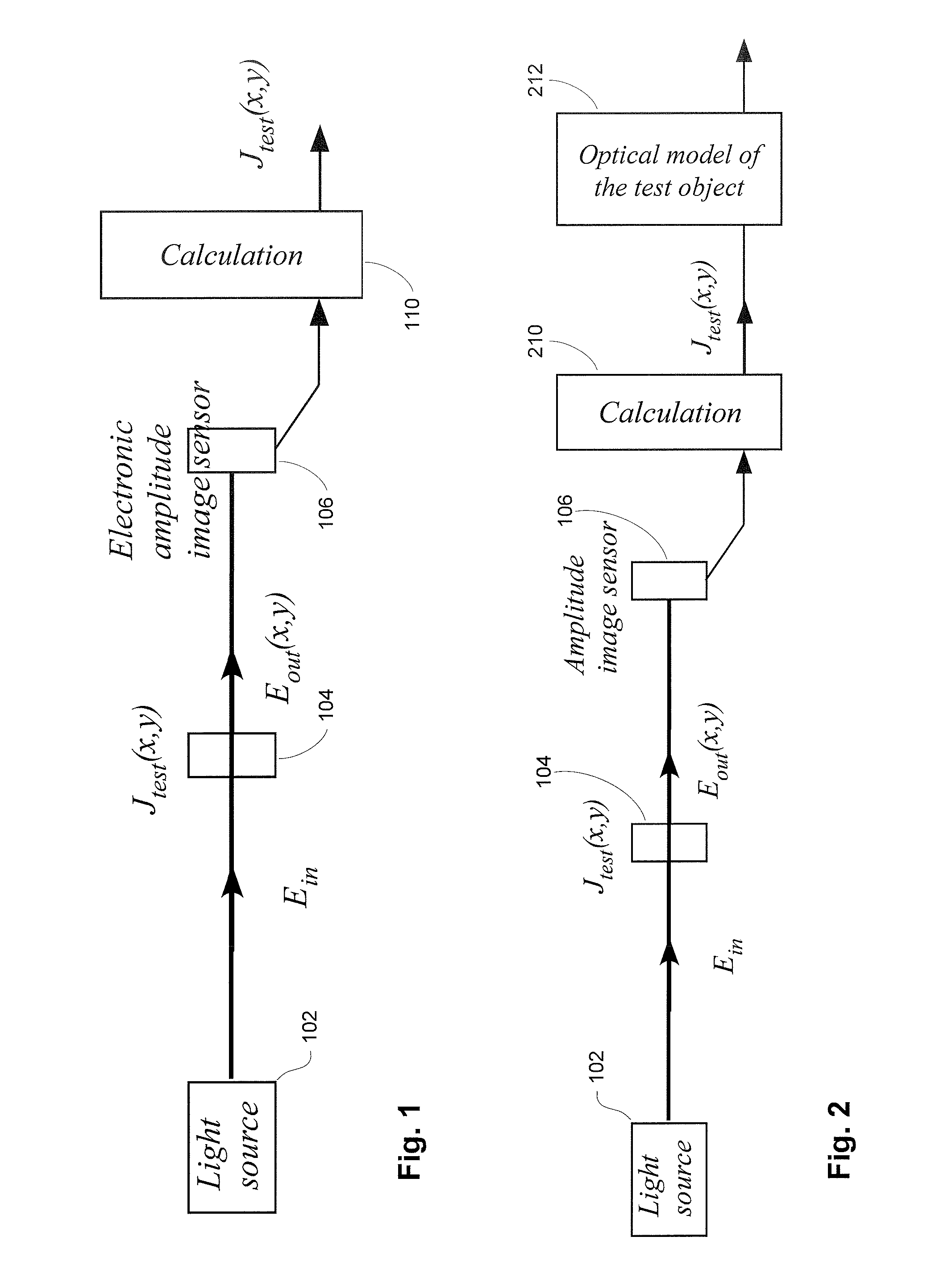
[0038]FIG. 1 shows a system for measuring the polarization and phase properties of a test sample, and how they vary across the surface, e.g. the Jones matrix for every location on a surface with a common phase and amplitude reference. The system uses an electronic amplitude image sensor (106) to record the power, polarization and phase at each point. The light source (102) may be any light source, typically not fully polarized. It may be a pulse source, such as an excimer or solid state laser, or a continuous one. Some light sources may have high coherence and others less coherence. The test sample (104) is illuminated by the light source. It typically is a surface, either in reflected or transmitted mode. Two varieties of electronic amplitude image sensors are depicted in FIGS. 8-9. The calculation module (110) takes as input the data collected in one or more samplings from the image sensor. It outputs a bit map with polarization, power and phase data at the pixels. A Jones matrix ...


PUM


Abstract

This application discloses a new method to record an image. It relates to microscopy and surface analysis in many scientific and technical fields. In particular it relates to the imaging and inspection of surfaces used in microelectronics: non-patterned and patterned wafers and photomasks. In the sense that it records electric amplitude, it relates to holography. Applications include microscopy, defect inspection, scatterometry, and optical metrology.

Description

RELATED APPLICATION[0001]This application claims priority to and the benefit of U.S. Provisional Application No. 60 / 796,179, filed 28 Apr. 2006, with a title substantially the same as this application, and naming as inventor (for U.S. purposes) Torbjorn Sandstrom. The provisional application is hereby incorporated by reference.BACKGROUND OF THE INVENTION[0002]This application discloses a new method to record an image. It relates to microscopy and surface analysis in many scientific and technical fields. In particular it relates to the imaging and inspection of surfaces used in microelectronics: non-patterned and patterned wafers and photomasks. In the sense that it records electric amplitude, it relates to holography. Applications include microscopy, defect inspection, scatterometry, and optical metrology.[0003]This work improves on interferometry, e.g. white-light interferometry, where successive interferograms with a phase-shift between them are used to construct an image which co...

Claims


Application Information

Patent Timeline
Patent Type & Authority Applications(United States)
IPC IPC(8): G01M19/00G01J3/42G01M99/00
CPCG01J4/04G01J9/02G01N21/21G01N21/9501G01B2290/45G01B9/0209G01B9/02011G01B2290/70G01N2021/95676G01B9/02G01B11/00G01N21/00
Inventor SANDSTROM, TORBJORN
Owner MICRONIC LASER SYST AB
Why Eureka
Try Eureka