

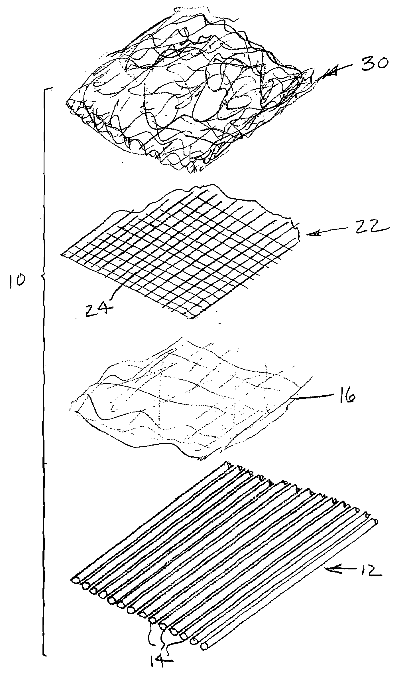
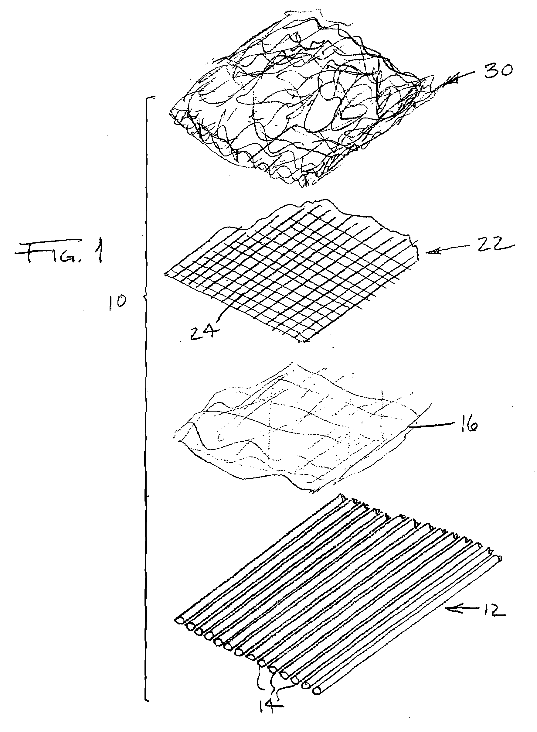
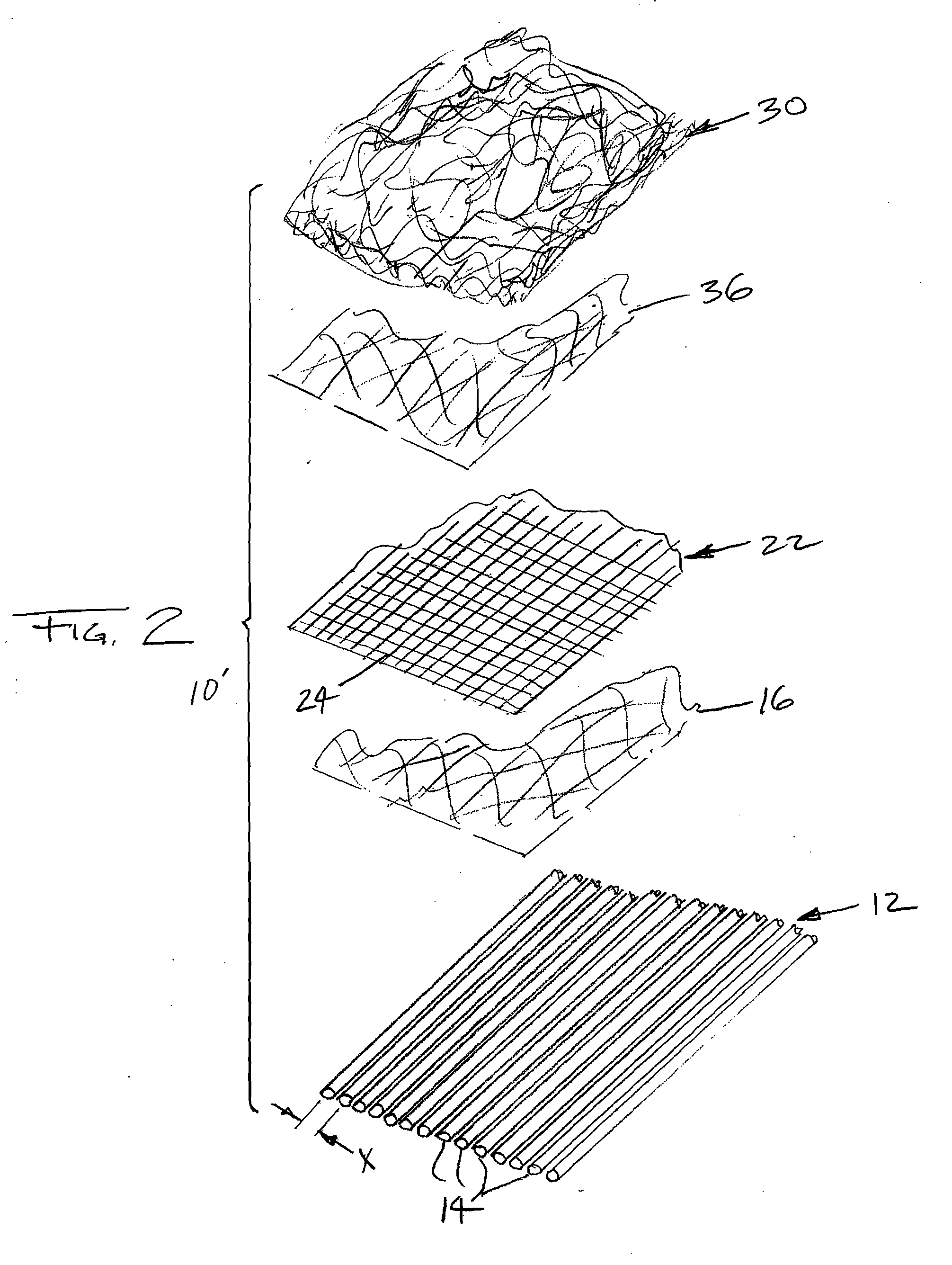
Nonwoven textile assembly, method of manufacture, and spirally wound press felt comprised of same
a technology of press felt and nonwoven textiles, which is applied in the field of industrial textiles, can solve the problems of affecting the pressure uniformity of the fabric, difficult control of cd and vertical (z-direction) spacing of nonwoven parallel yarns of arrays, and difficult support of nonwoven parallel yarns
- Summary
- Abstract
- Description
- Claims
- Application Information
AI Technical Summary
Benefits of technology
Problems solved by technology
Method used
Image

Examples
Embodiment Construction
[0053]Certain terminology is used in the following description for convenience only and is not considered limiting. The words “lower” and “upper” designate directions in the drawings to which reference is made. “CD” refers generally to the cross-direction of a moving belt, for example in papermaking machines, and “MD” refers to the machine direction or direction of travel of a moving belt, such as a papermaking fabric in a papermaking machine. As used herein, the recitation of “at least one of A, B, and C” means A, B, or C or any combination thereof, where A, B and C are specifically referenced elements herein. Additionally, the terms “a” and “one” are defined as including one or more of the referenced item unless specifically noted. The term “yarn fill” refers to the amount of yarns in a given space, relative to the total space considered; a yarn fill of 100% means that the space available is completely filled with yarns (i.e., the yarns are edge-to-edge). It is possible to have ya...
PUM
| Property | Measurement | Unit |
|---|---|---|
| angle | aaaaa | aaaaa |
| angle | aaaaa | aaaaa |
| angle | aaaaa | aaaaa |
Abstract
Description
Claims
Application Information