Remote diagnostic & treatment system

a technology applied in the field of remote diagnosis and treatment system, can solve the problem that no currently available product does not offer doctors

Inactive Publication Date: 2007-11-01
RADIO DIGITAL TECHN
View PDF21 Cites 105 Cited by
  • Summary
  • Abstract
  • Description
  • Claims
  • Application Information

AI Technical Summary

Benefits of technology

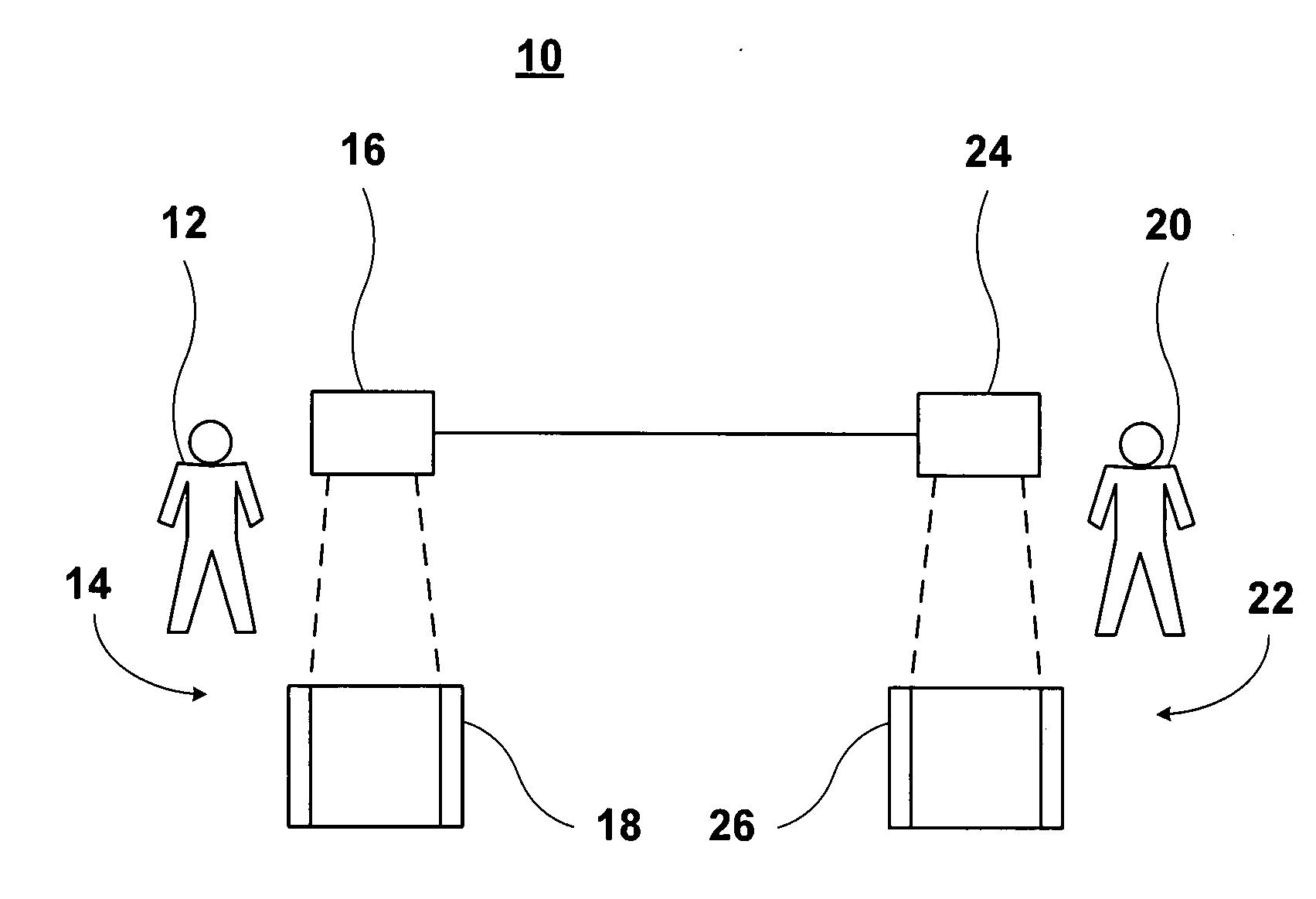
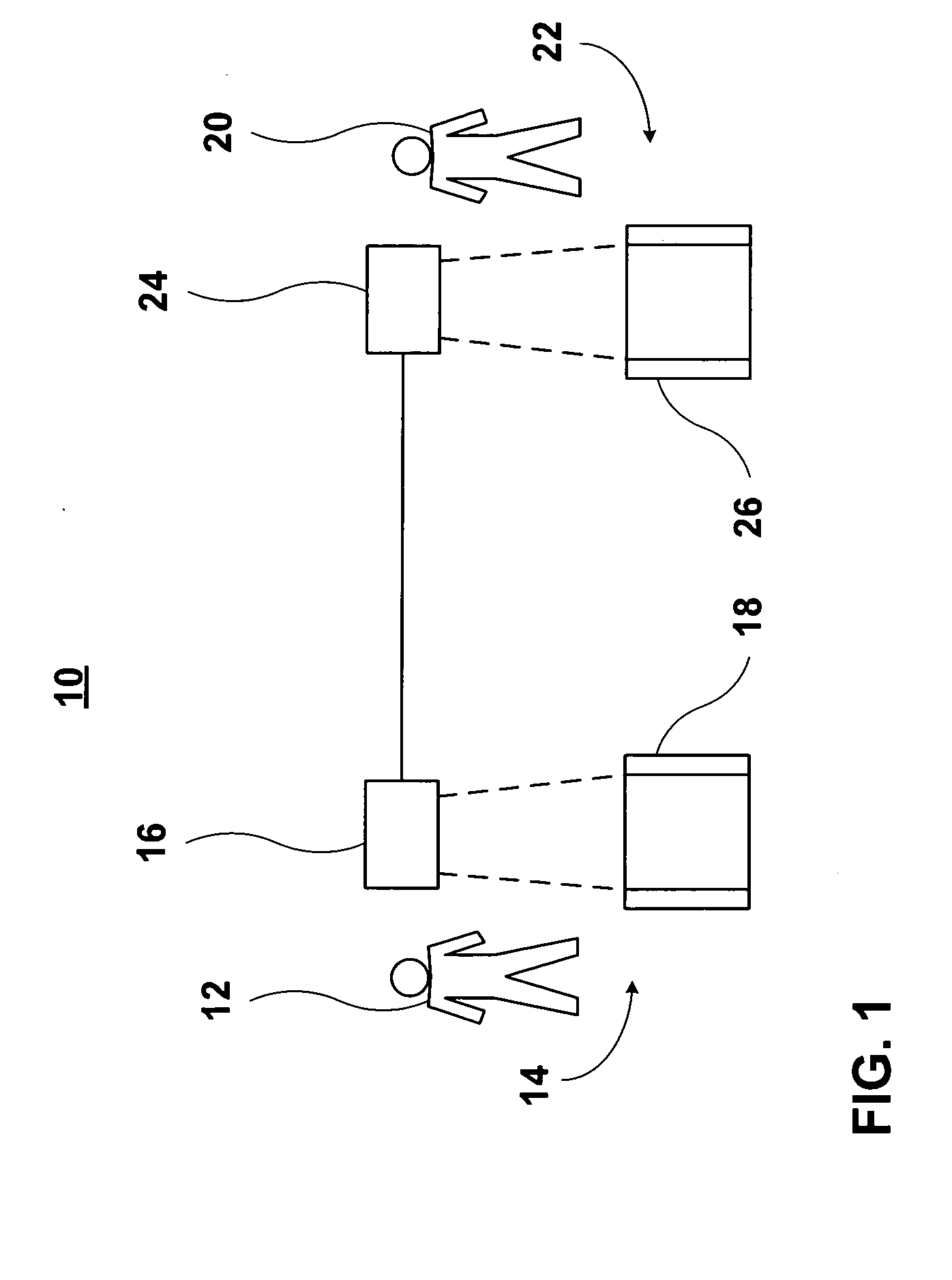
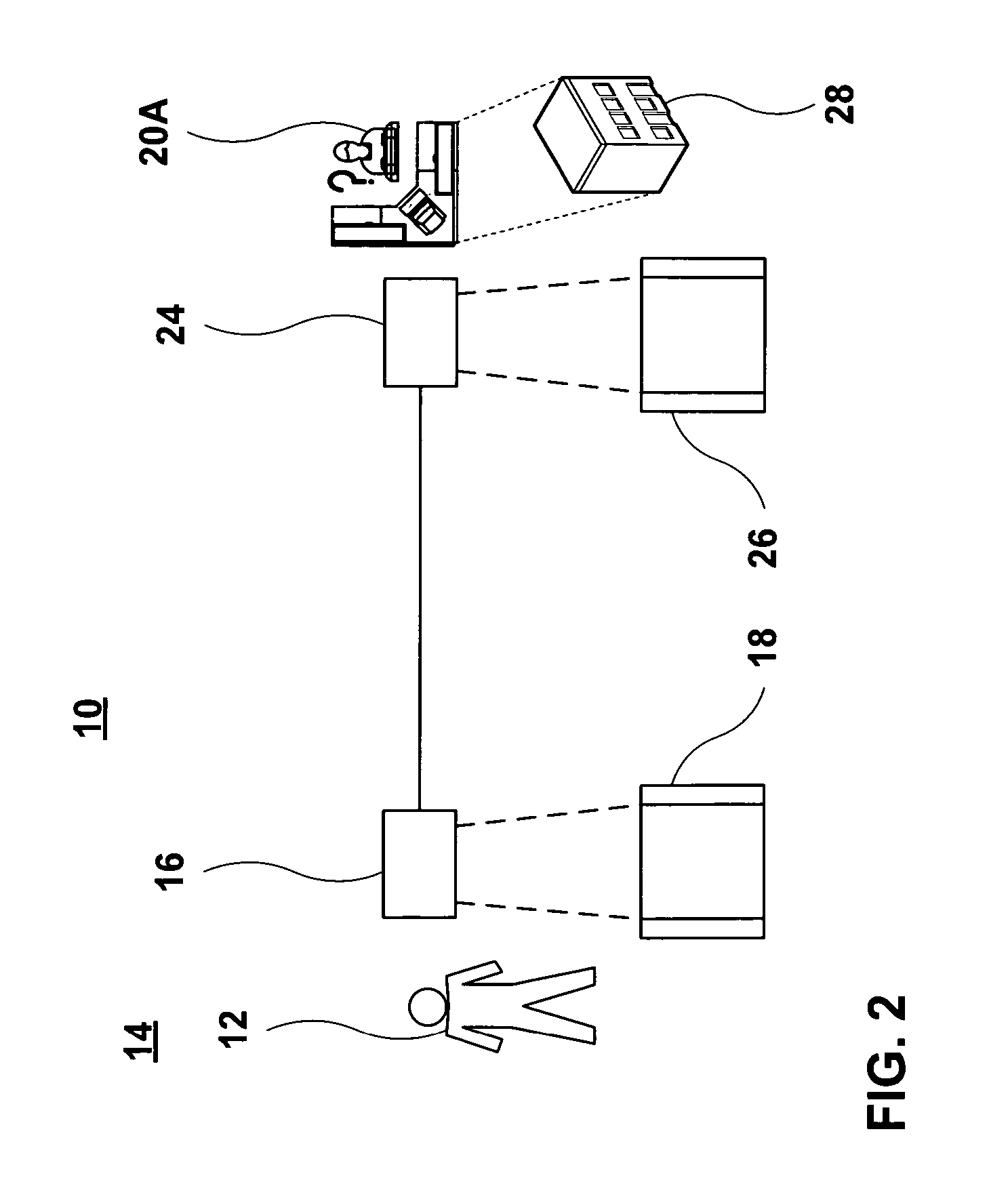
[0007] One embodiment of the present invention comprises a cellular telephone that includes a camera, a display, a speaker, a microphone and embedded remote control and diagnostic and treatment software. In an alternative embodiment, the invention may also include a variety of data devices which are connected to the cellular phone over a wired or wireless connection. In one embodiment, an operator at a call center may partially or jointly control the cellular telephone and / or a data device.
[0008] An appreciation of the other aims and objectives of the present invention and a more complete and comprehensive understanding of this invention may be obtained by studying the following description of a preferred embodiment, and by referring to the accompanying drawings.

Problems solved by technology

No currently available product offers doctors, nurses, medical technicians or other health care providers a simple and versatile method and apparatus that will collect data and then provide diagnostic and treatment assistance at virtually any location over a wireless connection.

Method used


Image

  • Remote diagnostic & treatment system
  • Remote diagnostic & treatment system
  • Remote diagnostic & treatment system

Examples


first embodiment

[0162] a wired connection between an data device 88 and a device or terminal 16 is Universal Serial Bus (USB) 90D, an external bus standard that supports data transfer rates of 12 Mbps for up to one hundred twenty-seven peripheral devices.

second embodiment

[0163] a wired connection between an data device 88 and a device or terminal 16 is FireWire 84E, IEEE 1394, High Performance Serial Bus. FireWire provides a single plug-and-socket connection on which up to sixty-three devices can be attached with data transfer speeds up to four hundred megabits per second.

[0164] Wired connections 90D, 90E between data devices 88 and the device or terminal 16 are shown in FIG. 14.

[0165] For each of the data devices 88 to connect 90 to a remote device or terminal 16, there must be a connection interface device 92 that accepts the data from the data device 88, and configures it for the connection 90 to the device or terminal 16.

[0166]FIG. 15 shows a functional block diagram 94 for the connection interface device 92. Device data input 96 is fed to a preamplifier 98 and then an amplifier 100. Thereafter the amplified data input 96 is fed into the appropriate interface 102 for the connection 90 to be used; the Bluetooth interface 102A for Bluetooth 90A,...

third embodiment

[0205]FIG. 26 shows a functional block diagram 108 of embedded software 18A that enables remote functional control of the data devices 88 for the diagnostic means 16A as well as a software application 26A that enables remote functional control of the data devices 88 connected to the diagnostic means 16AA. The functions shown in 108A are deployed as a component of 18A, the software embedded in a cellular and PCS wireless phone 16B; those in 108B as a component of the diagnostic, display and control software application 26A.

[0206] The functions 46 embedded in a cellular or PCS wireless phone 16B for controlling the data device 88 the weight scale 88C include, but are not limited to: [0207] Turn the scale 88C on or off 46R; [0208] Capture and send the weight reading 46S; and [0209] Turn the weight reading display 46T on or off.

[0210] The functional control means 82 in the diagnostic, display and control software application 26A for remotely controlling the scale 88C via a cellular or ...


PUM


Abstract

Methods and apparatus for providing remote diagnosis and treatment are disclosed. One embodiment of the invention comprises a cellular telephone (16A) that includes a camera (34), a display (40), a speaker (36A), a microphone (36B) and embedded diagnostic and treatment software (18). An alternative embodiment may also include one or more data devices (88) that may be connected to the cellular phone (16A) using a wireless (30A) or wired (30B) connection.

Description

INTRODUCTION [0001] The title of this Non-Provisional Patent Application is Remote Diagnostic & Treatment System. The Applicants are Richard L. Anglin, Jr., 2115 Heather Lane, Del Mar, Calif. 92014-2244 and Bradley T. Tipler, 4165 Pilon Point, San Diego, Calif. 92130-2205. Mr. Anglin is a Citizen of the United States of America; Mr. Tipler is a Citizen of Canada. FIELD OF THE INVENTION [0002] One embodiment of the present invention pertains to methods and apparatus for providing a remote diagnostic and treatment system. More particularly, one embodiment of the invention comprises a cellular telephone which includes a camera, a display, a speaker, a microphone and embedded remote control and diagnostic and treatment software. In an alternative embodiment, the invention may also include a variety of data devices which are connected to the cellular phone over a wired or wireless connection. FEDERALLY SPONSORED RESEARCH OR DEVELOPMENT [0003] None. BACKGROUND OF THE INVENTION [0004] Some...

Claims


Application Information

Patent Timeline
Patent Type & Authority Applications(United States)
IPC IPC(8): A61B5/00
CPCG06F19/3418G16H10/60G16H40/67
Inventor ANGLIN, RICHARD L. JR.TIPLER, BRADLEY T.
Owner RADIO DIGITAL TECHN
Why Eureka
Try Eureka