
Apparatus for and method of filling hydrogen tank with hydrogen

a hydrogen tank and apparatus technology, applied in the field of apparatus and methods for filling hydrogen tanks, can solve the problems of high cost, high labor intensity, and high labor intensity, and achieve the effect of suppressing temperature changes inside the hydrogen tank and quick filling

Inactive Publication Date: 2007-11-08
HONDA MOTOR CO LTD
View PDF1 Cites 40 Cited by
  • Summary
  • Abstract
  • Description
  • Claims
  • Application Information

AI Technical Summary

Benefits of technology

[0008] It is a general object of the present invention to provide an apparatus and method for quickly filling a hydrogen tank with hydrogen at temperatures that are suitable for suppressing temperature changes inside the hydrogen tank as it is being filled.
[0009] A major object of the present invention is to provide an apparatus and method for filling a hydrogen tank with hydrogen, which holds the interior of the hydrogen tank substantially at the atmospheric temperature immediately after completion of filling the hydrogen tank, while also ensuring that the hydrogen tank is filled with a sufficient amount of hydrogen.

Problems solved by technology

When the above temperature rise occurs, therefore, the filled hydrogen tank is likely to suffer a shortage of hydrogen.
Consequently, a considerable time elapses after it is determined that the interior of the hydrogen tank needs to be cooled and until the hydrogen tank is filled sufficiently with cooled hydrogen.
It is quite time-consuming to fill the hydrogen tank with hydrogen at the atmospheric temperature.
Therefore, the conventional hydrogen supply station is disadvantageous in that the temperature of the hydrogen used to fill the hydrogen tank is not highly responsive to temperature increases and decreases inside the hydrogen tank as it is being filled.
Thus, the hydrogen tank cannot be filled with hydrogen while responding quickly to temperature changes inside the hydrogen tank.

Method used


Image

  • Apparatus for and method of filling hydrogen tank with hydrogen
  • Apparatus for and method of filling hydrogen tank with hydrogen
  • Apparatus for and method of filling hydrogen tank with hydrogen

Examples


Embodiment Construction

[0029] A hydrogen tank filling apparatus according to an embodiment of the present invention, and hydrogen tank filling methods carried out by the hydrogen tank filling apparatus, will be described in detail below with reference to the accompanying drawings.

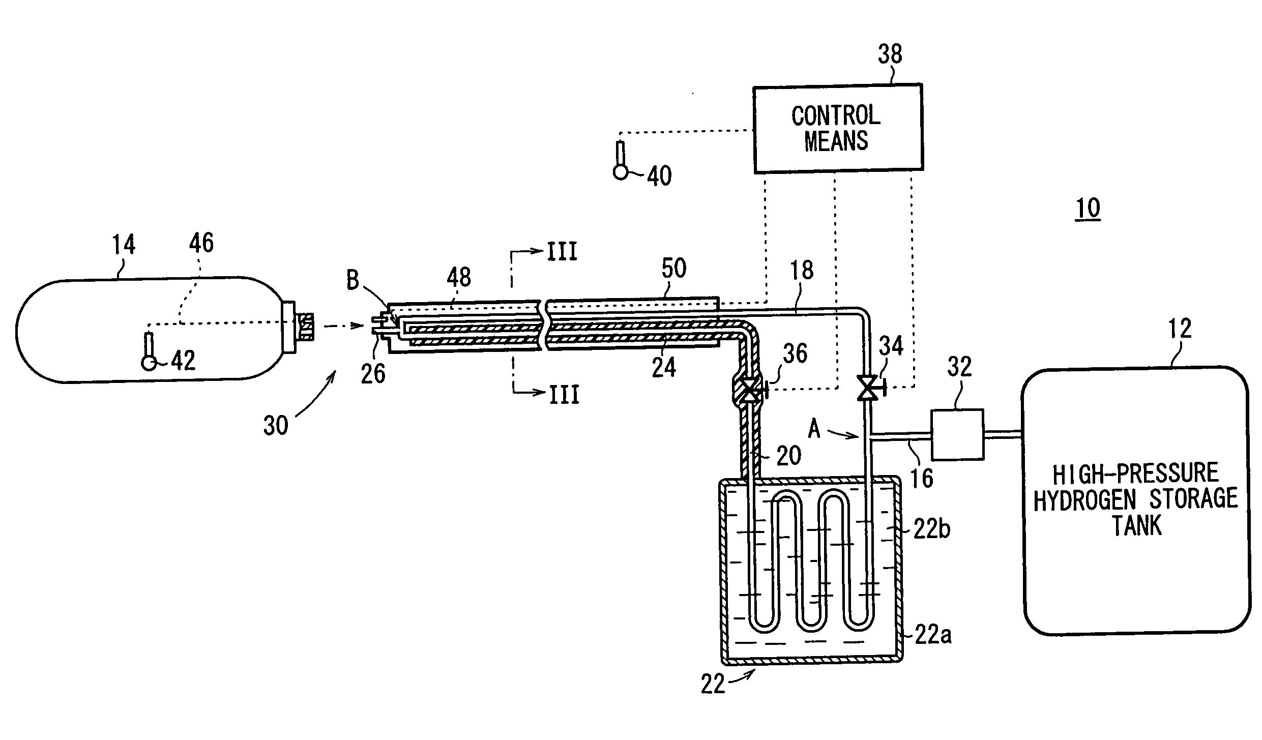
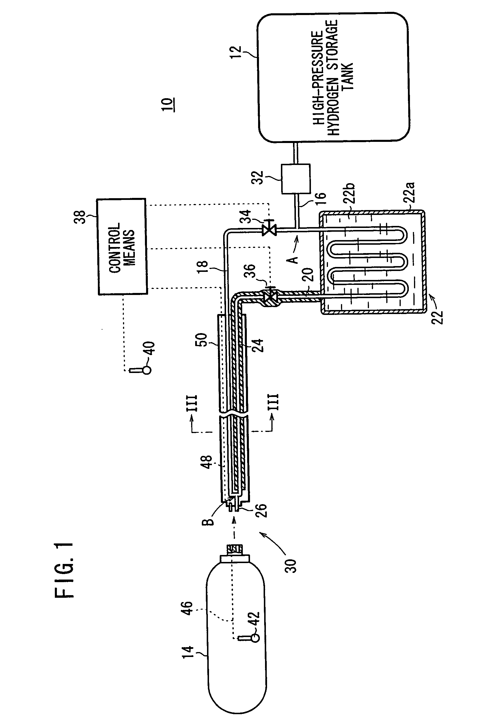
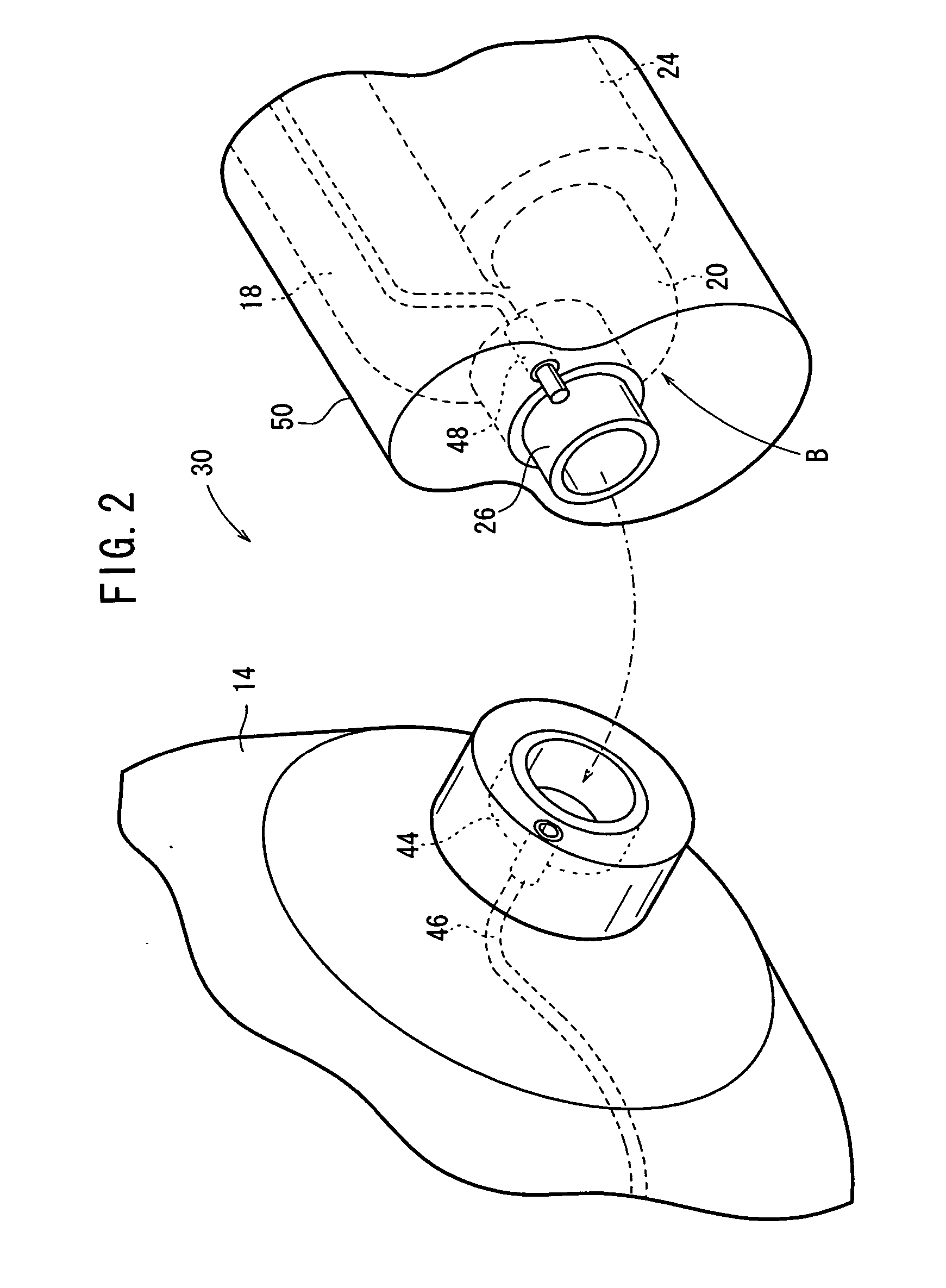
[0030] As shown in FIG. 1, a hydrogen tank filling apparatus 10 according to an embodiment of the present invention serves to supply hydrogen from a high-pressure hydrogen storage tank 12, which is a high-pressure hydrogen storage unit for storing hydrogen under a high pressure, to a hydrogen tank 14, which stores hydrogen under a pressure lower than that of the high-pressure hydrogen storage tank 12. The hydrogen tank 14 stores and supplies hydrogen as a fuel gas to a fuel cell, for generating electrical energy by an electrochemical reaction between hydrogen and oxygen. The hydrogen tank 14 may be of any structure capable of storing hydrogen, e.g., a tank for storing hydrogen under high pressure, a tank containing a hydrogen st...


PUM

PropertyMeasurementUnit
Temperatureaaaaaaaaaa
Thermal insulatoraaaaaaaaaa

Abstract

An hydrogen tank filling apparatus includes a first hydrogen supply pipe for supplying hydrogen substantially at an atmospheric temperature from a high-pressure hydrogen storage tank to a hydrogen tank, a second hydrogen supply pipe for supplying cooled hydrogen from the high-pressure hydrogen storage tank to the hydrogen tank, and an internal tank temperature measuring unit for measuring the temperature inside the hydrogen tank. The first hydrogen supply pipe and the second hydrogen supply pipe are selectively switched by a control unit, depending on changes in the temperature inside the hydrogen tank.

Description

BACKGROUND OF THE INVENTION [0001] 1. Field of the Invention [0002] The present invention relates to an apparatus and method for filling a hydrogen tank with hydrogen. [0003] 2. Description of the Related Art [0004] Generally, a fuel cell, which generates electrical energy by an electrochemical reaction between hydrogen and oxygen, is supplied with hydrogen as a fuel from a hydrogen tank, which is located near the fuel cell and which stores hydrogen under a high pressure. When the amount of hydrogen that is stored in the hydrogen tank decreases, the hydrogen tank is connected to a high-pressure hydrogen storage tank, which stores hydrogen under a pressure higher than the hydrogen tank. Thus, the hydrogen tank is replenished with hydrogen supplied from the high-pressure hydrogen storage tank. [0005] It is known in the art that when the hydrogen tank is filled with high-pressure hydrogen from the high-pressure hydrogen storage tank, the hydrogen inside the filled hydrogen tank generat...

Claims


Application Information

Patent Timeline
IPC IPC(8): F17C1/00B65B31/00B65B1/28B62D33/00G08B21/00
CPCF17C5/06Y02E60/321F17C13/026F17C2205/0376F17C2221/012F17C2223/0123F17C2223/036F17C2225/0123F17C2225/036F17C2227/0341F17C2227/0353F17C2227/0388F17C2227/047F17C2250/032F17C2250/0439F17C2250/0626F17C2260/025F17C2265/022F17C2270/0184F17C2270/0763F17C7/00Y02P90/45Y02E60/32
Inventor KANOYA, IZURUHOSOE, MITSUYA
Owner HONDA MOTOR CO LTD
Learn More