Power generation pad using wasted energy

a power generation pad and energy waste technology, applied in the direction of mechanical energy handling, mechanical equipment, machines/engines, etc., can solve the problems of inefficiency of such systems, inability to meet the needs of hydropower,

Inactive Publication Date: 2007-11-08
KIM RICHARD H +3
View PDF22 Cites 40 Cited by
  • Summary
  • Abstract
  • Description
  • Claims
  • Application Information

AI Technical Summary

Problems solved by technology

Hydropower and wind power both hold promise as relatively speaking “clean” sources of energy, however, even wind energy farms kill countless birds every years, while suitable locations for hydropower (dams) are frustratingly limited.
However, most of these schemes involve devices which are either inefficient at producing energy or are excessiv

Method used


Image

  • Power generation pad using wasted energy
  • Power generation pad using wasted energy
  • Power generation pad using wasted energy

Examples


first embodiment

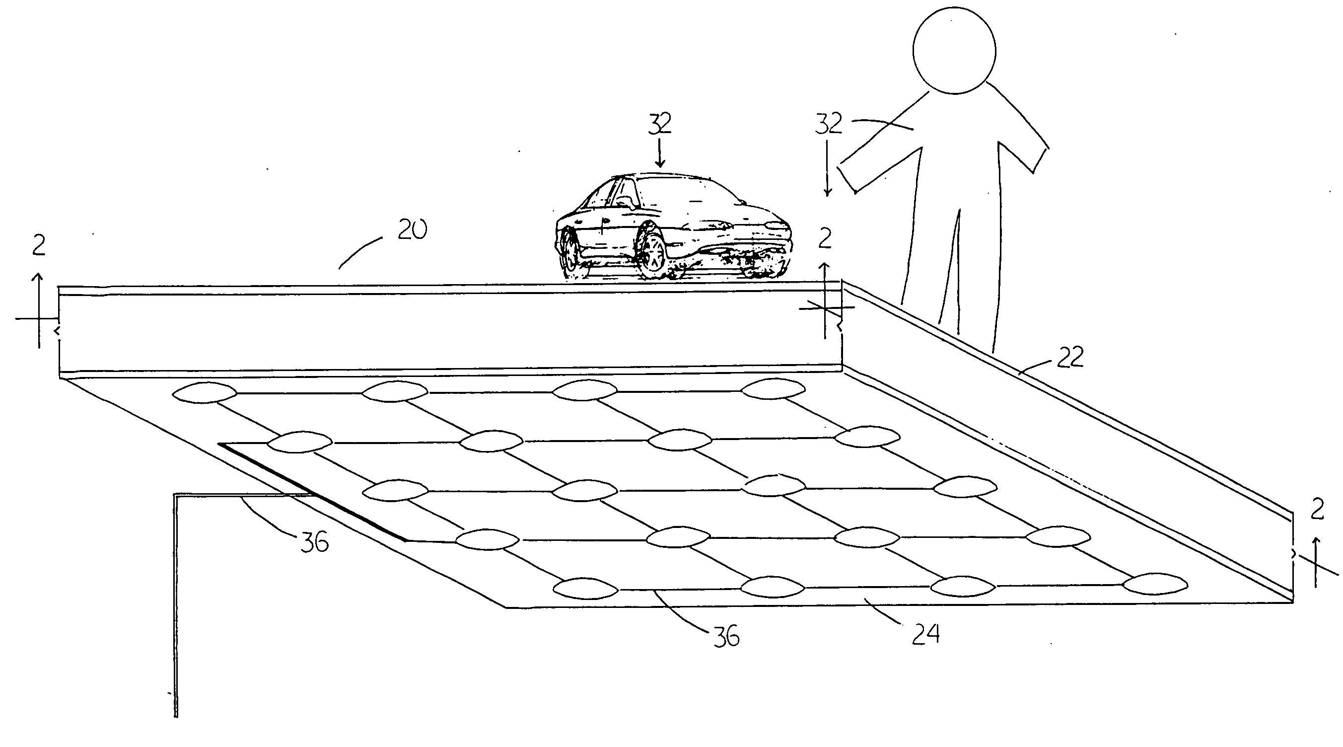
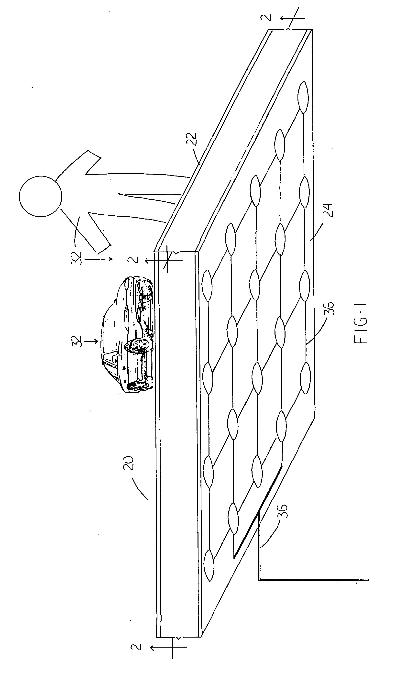
[0065]FIG. 1 is a low-angle perspective diagram of the energy generation device 20. Partially flexible top surface 22 is a traffic surface on which traffic 32, pedestrian or vehicular, may pass. It may be flat, bumpy, waved, grooved, patterned, or combinations thereof. Bottom surface 24 may be an inflexible material such as sidewalk, paving, tarmac, road, street, highway, intersection, metal plate, stone, wood, polymer and combinations thereof and in any location in which people or vehicles regularly pass. Thus the device may be made as a retrofit to sidewalks and streets, or it may be built integral with the street, and it may be even be a portable pad which may be temporarily placed in one location before being moved to another location.

[0066]Electrical connection / electrical connection to load 36 may be standard wiring which connects dynamo cells as required or / and which connects the device to an electrical load such as a light, an emergency telephone, a sign, an electrical power ...

second embodiment

[0070]FIG. 3 is a partially cross-sectional low-angle perspective diagram of the device. It may be clearly seen in this embodiment that the individual dynamos of the dynamo cells may be of differing construction. FIG. 4 is a block diagram of a storage battery connected to the device. FIG. 5 is an exploded view of a storage battery.

[0071]Energy generator 120 once again has partially flexible top surface 122, bottom surface 124, spring 126, magnet 128, coil 130, plunger heads 138, bottom support 140, and a network of electrical connections and connections to load, 136.

[0072]Control circuitry 142 may be disposed in the load, which may be battery 144 having battery circuit panel 146 or may be in the generation device 120 itself, or in embodiments may be omitted if practicable.

[0073]The FIG. 6 in general show that the construction of the individual dynamos may vary.

[0074]FIG. 6a1 is a transparent view of a third embodiment of one individual dynamo of the invention. FIG. 6a2 is a cross-se...


PUM


Abstract

The present invention teaches an energy generator comprising a generally flat and partially flexible traffic surface on which pedestrians and traffic may pass. Underneath the traffic surface, a plurality of dynamo cells each have a dynamo therein, each dynamo having two electricity generating elements (magnets, coils, etc) and an operative electrical connection to an electrical load such as a battery, capacitor, light, an electrical network or the like. A first electrical generating element in each dynamo may be disposed so that it moves downward when weight from traffic is applied to the traffic surface, while a second electricity generating element remains stationary supported. by the bottom surface of the energy generator. A spring and bottom support may urge the first (moving) element back upwards when the imposed force is released.

Description

CROSS-REFERENCE TO RELATED APPLICATIONS[0001]The application claims the priority and benefit of U.S. Provisional Patent Application No. 60 / 798704 filed May 8, 2006 in the name of the same inventors, and entitled WASTING ENERGY RECYCLE POWER GENERATING PAD the entire specification of which is incorporated by reference herein.COPYRIGHT NOTICE[0002]A portion of the disclosure of this patent document contains material which is subject to copyright protection. The copyright owner has no objection to the facsimile reproduction by anyone of the patent document or the patent disclosure, as it appears in the Patent and Trademark Office patent file or records, but otherwise reserves all copyright rights whatsoever. 37 CFR 1.71(d).FIELD OF THE INVENTION[0003]This invention relates generally to energy generation devices, and specifically to waste energy recycling devices.STATEMENT REGARDING FEDERALLY FUNDED RESEARCH[0004]This invention was not made under contract with an agency of the US Govern...

Claims


Application Information

Patent Timeline
IPC IPC(8): H02K7/18F03G7/08F02B63/04
CPCF03G7/08H02K35/02H02K7/1876F03G5/06F03G7/087F03G5/063
Inventor KIM, RICHARD H.KIM, BOBBYKIM, MIKE S.KIM, DEBRA Y.
Owner KIM RICHARD H
Why Eureka
Try Eureka