
Noise reduction for analyte detection systems

Inactive Publication Date: 2007-11-08
OPTISCAN BIOMEDICAL
View PDF4 Cites 81 Cited by
  • Summary
  • Abstract
  • Description
  • Claims
  • Application Information

AI Technical Summary

Benefits of technology

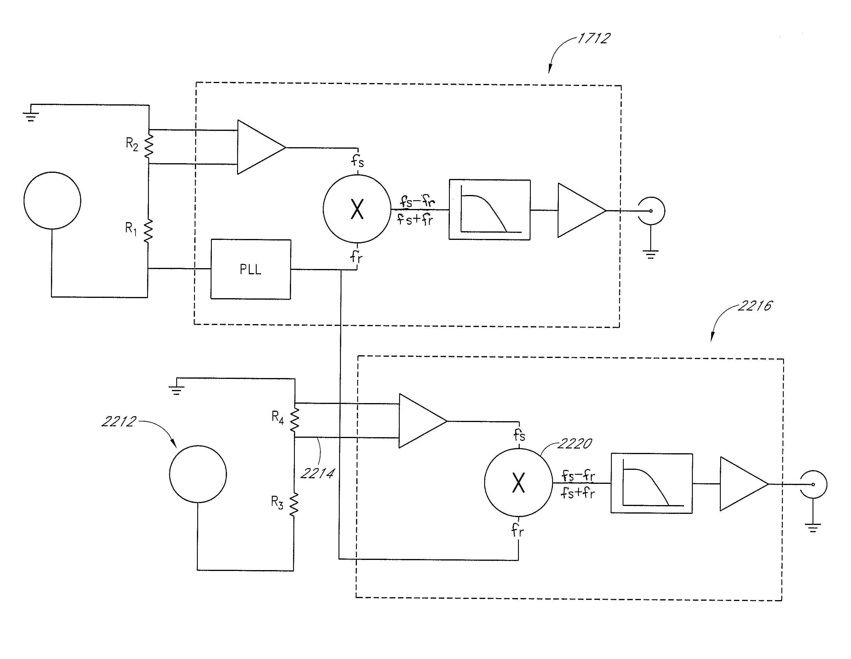
[0007] Some embodiments use a synchronous demodulator and digital filter to reduce microphonic signal content. Some embodiments monitor the microphonic signal content and “holds off” on making a measurement until vibrations subside. In some embodiments, monitoring is performed using an accelerometer or other vibration sensor. In another embodiment, an algorithm is used to examine the detector output signal and detect excessive microphonic components thereby eliminating the need for the accelerometers.
[0009] Some embodiments comprise a system for improving accuracy of a mobile analyte concentration measurement apparatus. The system can comprise: a sample detector configured to provide a detector output signal; a first signal conditioner configured to receive the detector output signal; a vibration sensor mounted to detect vibration of the sample detector and configured to provide a sensor output signal; a second signal conditioner configured to receive the sensor output signal; and a controller configured to communicate with the sample detector and the vibration sensor and prevent the sample detector from detecting when the sensor output signal exceeds a threshold value.
[0010] Some embodiments comprise a method of mitigating the effects of vibration on an optical analyte detection system measurements. The method can comprise: monitoring microphonic effects to determine when a threshold is exceeded; and automatically delaying optical measurement until after the threshold is no longer exceeded. In some embodiments, monitoring microphonic effects comprises processing a detector output signal. In some embodiments, monitoring microphonic effects comprises monitoring output from a vibration sensor that is physically associated with a detector. In some embodiments, monitoring output from a vibration sensor further comprises monitoring output from an accelerometer.

Problems solved by technology

This can be done in a hospital or clinical setting when there is a risk that the levels of certain analytes may move outside a desired range, which in turn can jeopardize the health of a patient.
Currently known systems for analyte monitoring in a hospital or clinical setting suffer from various drawbacks.

Method used


Image

  • Noise reduction for analyte detection systems
  • Noise reduction for analyte detection systems
  • Noise reduction for analyte detection systems

Examples


Embodiment Construction

[0034] Although certain preferred embodiments and examples are disclosed below, the inventive subject matter extends beyond the specifically disclosed embodiments to other alternative embodiments and / or uses of the invention, and to modifications and equivalents thereof. Thus, the scope of the inventions herein disclosed is not limited by any of the particular embodiments described below. For example, in any method or process disclosed herein, the acts or operations of the method or process may be performed in any suitable sequence and are not necessarily limited to any particular disclosed sequence. For purposes of contrasting various embodiments with the prior art, certain aspects and advantages of these embodiments are described. Of course, it is to be understood that not necessarily all such aspects or advantages are achieved by any particular embodiment. Thus, for example, it should be recognized that the various embodiments may be carried out in a manner that achieves or optim...


PUM


Abstract

Methods and apparatus are provided for determining the concentration of an analyte in a sample, such as an analyte in a sample of bodily fluid. Some embodiments use a synchronous demodulator and digital filter to reduce microphonic signal content. Some embodiments monitor the microphonic signal content and “hold off” on making a measurement until vibrations subside. Monitoring can be performed using an accelerometer or other vibration sensor. An algorithm can be used to examine the detector output signal and detect excessive microphonic components, making an accelerometer unnecessary.

Description

CROSS-REFERENCE TO RELATED APPLICATIONS [0001] This application claims priority to U.S. Provisional Patent Application No. 60 / 791,931, filed Apr. 11, 2006, the entirety of which is hereby incorporated by reference and made part of this specification.BACKGROUND [0002] 1. Field [0003] Some embodiments disclosed herein relate to methods and apparatus for determining the concentration of an analyte in a sample, such as an analyte in a sample of bodily fluid, as well as methods and apparatus which can be used to support the making of such determinations. [0004] 2. Description of the Related Art [0005] It is advantageous to measure the levels of certain analytes, such as glucose, in a bodily fluid, such as blood. This can be done in a hospital or clinical setting when there is a risk that the levels of certain analytes may move outside a desired range, which in turn can jeopardize the health of a patient. Currently known systems for analyte monitoring in a hospital or clinical setting suf...

Claims


Application Information

Patent Timeline
IPC IPC(8): G01N33/48
CPCA61B5/14532A61B5/1459G01N21/35G01N21/274G01N21/07
Inventor HEPPELL, KEVINBRAIG, JAMES
Owner OPTISCAN BIOMEDICAL
Learn More