Image-acquisition optical system

an optical system and image acquisition technology, applied in the field of image acquisition optical systems, can solve the problems of difficult to identify the region of the subject to be microscopically observed, difficult to completely immobilize the endoscope tip at the site to be observed, and difficult to identify the examination si

Active Publication Date: 2007-11-08
OLYMPUS CORP
View PDF2 Cites 36 Cited by
  • Summary
  • Abstract
  • Description
  • Claims
  • Application Information

AI Technical Summary

Benefits of technology

[0016] In view of the problems described above, the present invention provides a compact image-acquisition optical system with a short overall length and small lens o

Problems solved by technology

Furthermore, the endoscope image-acquisition optical systems for microscopic observation described in the above-mentioned Japanese Unexamined Patent Application, Publication No. 2004-313769 and Japanese Unexamined Patent Application, Publication No. 2004-313772 are only capable of close-up magnified observation at a fixed magnification.
As a result, with the endoscope image-acquisition optical systems for microscopic observation described in the above-mentioned Japanese Unexamined Patent Application, Publication No. 2004-313769 and Japanese Unexamined Patent Application, Publication No. 2004-313772, some parallax occurs between the viewing field of the endoscope and the viewing field of the microscope, which makes it difficult to identify the region of the subject to be microscopically observed.
Also, it is difficult to completely immobilize the tip of the endoscope at the site to be observed due to the effect of pulsing and so forth in the subject body.
Therefore, it

Method used


Image

  • Image-acquisition optical system
  • Image-acquisition optical system
  • Image-acquisition optical system

Examples


example 1

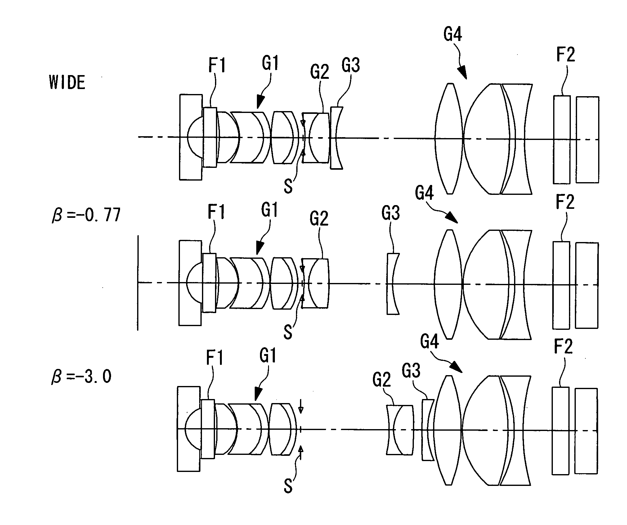
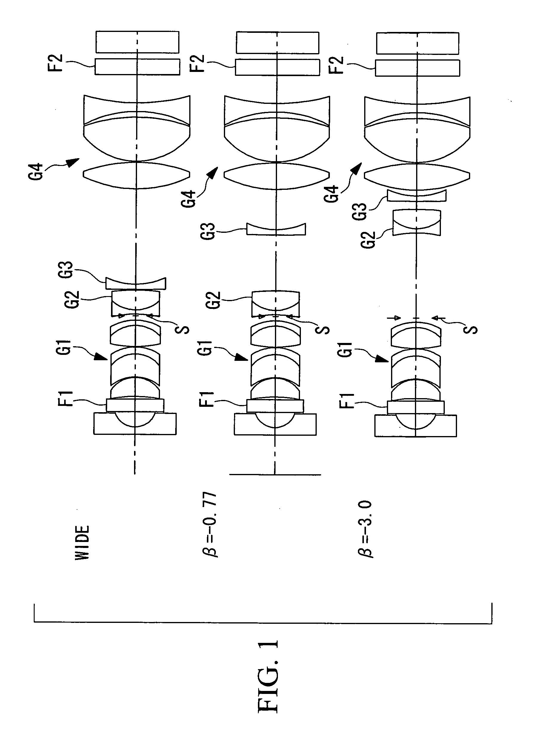
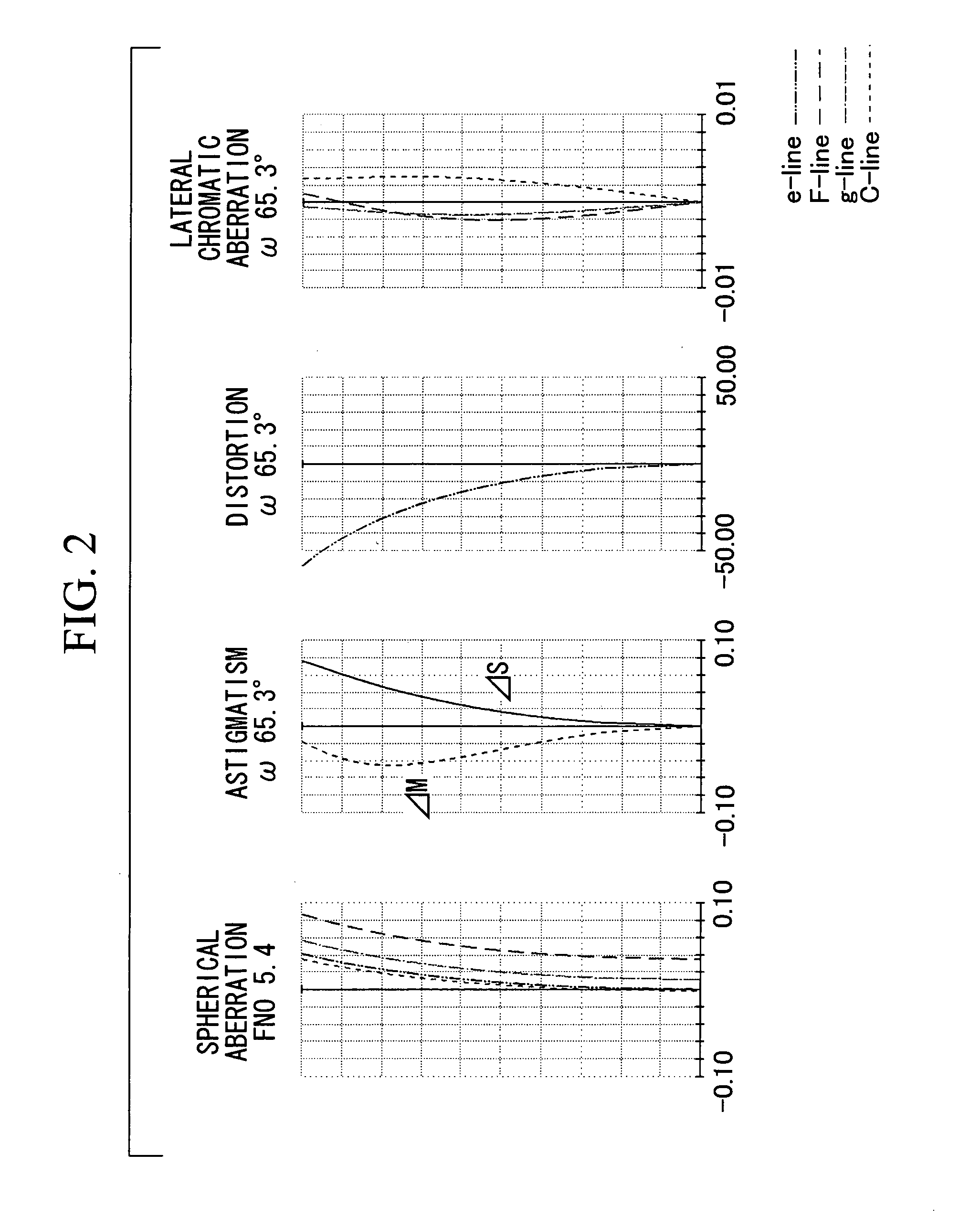
[0090] The configuration of a magnifying endoscope objective lens according to this Example is shown in FIG. 1. The design data of the magnifying endoscope objective lens according to this Example is shown in Table 2, and the values of variable parameters of the magnifying endoscope objective lens according to this Example in each observation state, that is, a normal observation state (wide-angle end), an intermediate state, and a close-up magnified-observation state (telephoto end), are shown in Table 3. FIGS. 2, 3, and 4 respectively show aberration curves in the normal observation state (wide-angle end), the intermediate state, and the close-up magnified-observation state (telephoto end) of the magnifying endoscope objective lens according to this Example. FIG. 1 shows the configuration of the magnifying endoscope objective lens according to this Example in the normal observation state (wide-angle end), the intermediate state, and the close-up magnified-observation state (telepho...

example 2

[0098] The configuration of a magnifying endoscope objective lens according to this Example is shown in FIG. 5. The design data of the magnifying endoscope objective lens of this Example is shown in Table 4, and the values of variable parameters of the magnifying endoscope objective lens according to this Example in each state, that is, the normal observation state (wide-angle end), the intermediate state, and the close-up magnified observation state (telephoto end), are shown in Table 5. FIGS. 6, 7, and 8 respectively show aberration curves of the magnifying endoscope objective lens according to this Example in the normal observation state (wide-angle end), the intermediate state, and the close-up magnified-observation state (telephoto end). The configurations of the magnifying endoscope objective lens according to this Example in the normal observation state (wide-angle end), the intermediate state, and the close-up magnified-observation state (telephoto end) are shown in FIG. 5, ...

example 3

[0105] The configuration of a magnifying endoscope objective lens according to this Example is shown in FIG. 9. The design data of the magnifying endoscope objective lens of this Example is shown in Table 6, and the values of variable parameters of the magnifying endoscope objective lens according to this Example in each state, that is, the normal observation state (wide-angle end), the intermediate state, and the close-up magnified observation state (telephoto end), are shown in Table 7. FIGS. 10, 11, and 12 respectively show aberration curves of the magnifying endoscope objective lens according to this Example in the normal observation state (wide-angle end), the intermediate state, and the close-up magnified-observation state (telephoto end). The configurations of the magnifying endoscope objective lens according to this Example in the normal observation state (wide-angle end), the intermediate state, and the close-up magnified-observation state (telephoto end) are shown in FIG. ...


PUM


Abstract

There is provided a compact image-acquisition optical system which is capable of observing from normal observation to microscopic observation with a single image-acquisition optical system, whose overall length is short, and whose lens outer diameter is small. The invention provides an image-acquisition optical system comprising a plurality of lens groups, wherein, by moving at least one of the plurality of lens groups on the optical axis, it is possible to change a state from a normal observation state (wide-angle end) to a close-up magnified-observation state (telephoto end), and wherein the magnification of the image-acquisition optical system at the telephoto end satisfies βTELE<−2.0.

Description

BACKGROUND OF THE INVENTION [0001] 1. Field of the Invention [0002] The present invention relates to an image-acquisition optical system having a power varying function, and more particularly, relates to an image-acquisition optical system used in an endoscope objective lens that is capable of magnified observation or a photographic lens that is capable of macro photography, such as the lens of a digital camera, video camera, mobile-phone camera, or the like. [0003] This application is based on Japanese Patent Application No. 2006-092465, the content of which is incorporated herein by reference. [0004] 2. Description of Related Art [0005] In recent years there has been an increasing demand in the field of medical endoscopes for image-acquisition optical systems that are capable of magnified observation for precise diagnosis of lesions. Conventional examples of such image-acquisition optical systems for magnifying endoscopes are disclosed in Japanese Examined Patent Application, Publ...

Claims


Application Information

Patent Timeline
IPC IPC(8): G02B15/14
CPCG02B13/0045G02B23/2438G02B15/17G02B13/006
Inventor TAKATO, HIDEYASU
Owner OLYMPUS CORP
Why Eureka
Try Eureka