Plasma display panel device

a technology of display panel and plasma, which is applied in the direction of casing/cabinet/drawer details, casing/cabinet/drawer of electrical apparatus, instruments, etc., can solve the problem of rapid drop in device price, and achieve good heat discharging capability and good electrical functionality

Inactive Publication Date: 2007-11-08
SAMSUNG SDI CO LTD
View PDF14 Cites 42 Cited by
  • Summary
  • Abstract
  • Description
  • Claims
  • Application Information

AI Technical Summary

Benefits of technology

[0012]Aspects of the present invention provide a plasma display device having a good heat discharging capability, and an good electrical

Problems solved by technology

Also, improvements in the mass production of the LCD devi

Method used


Image

  • Plasma display panel device
  • Plasma display panel device
  • Plasma display panel device

Examples


Embodiment Construction

[0021]Reference will now be made in detail to the various embodiments of the present invention, examples of which are illustrated in the accompanying drawings, wherein like reference numerals refer to the like elements throughout. The embodiments are described below in order to explain the present invention, by referring to the figures

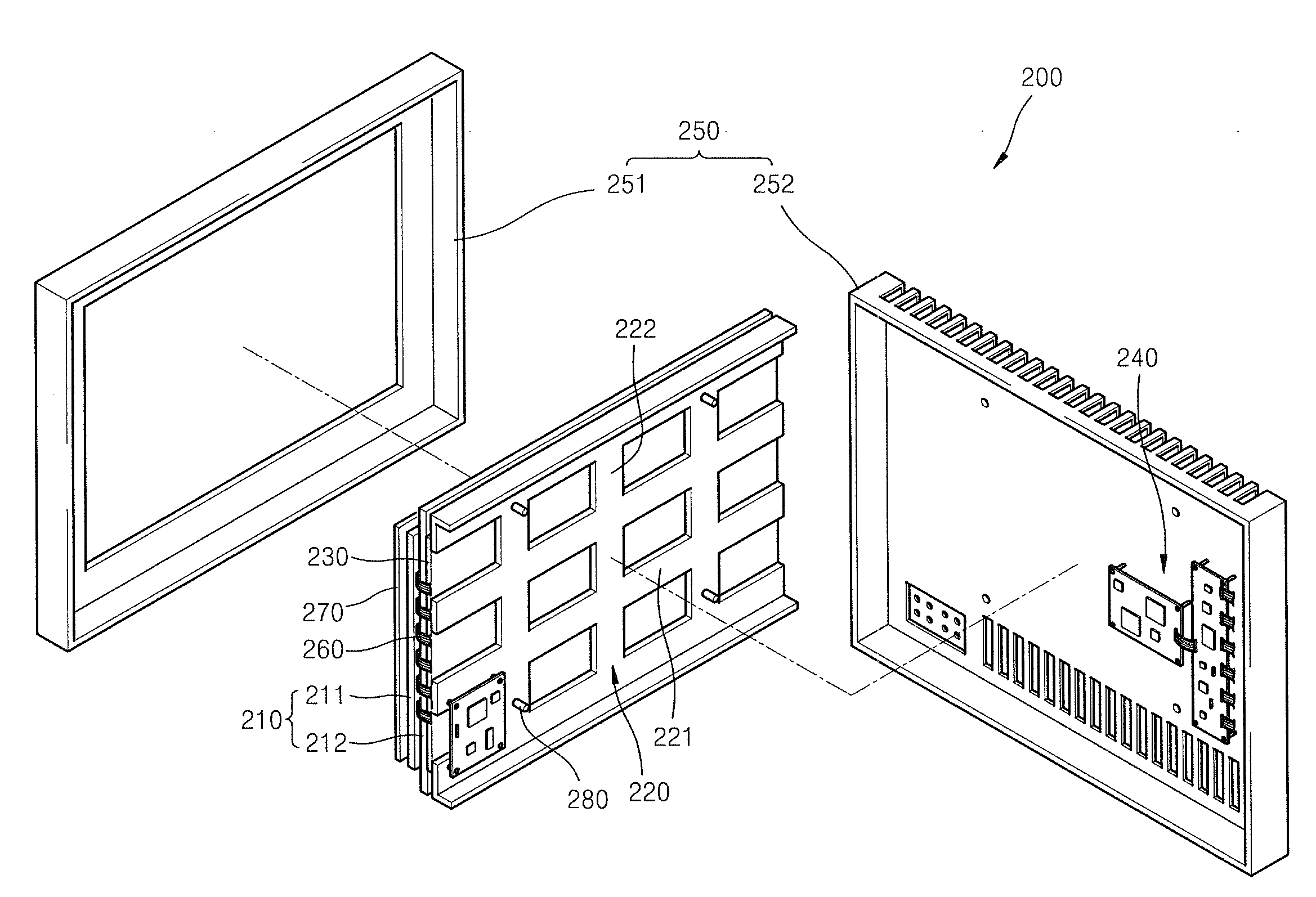
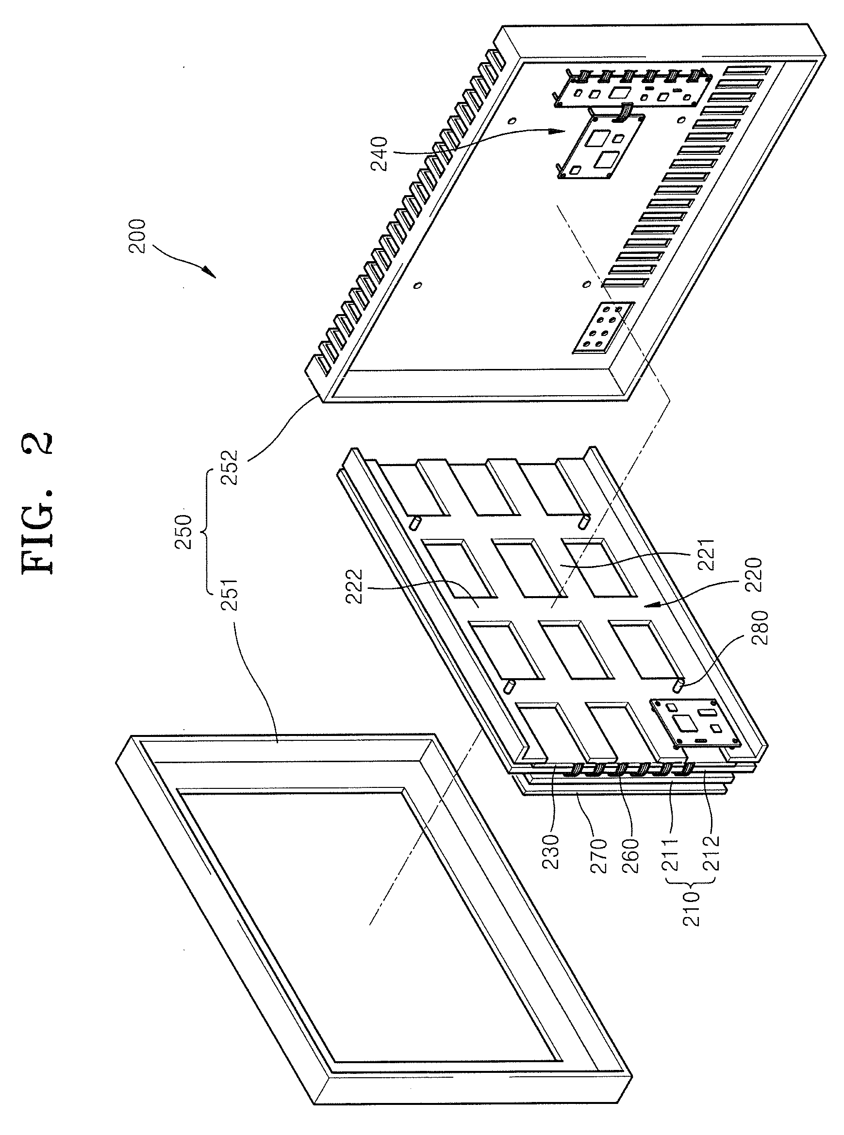
[0022]FIG. 2 is an exploded perspective view of a PDP device 200, according to an embodiment of the present invention. FIG. 3 is a cross-sectional view of the PDP device 200 when assembled.

[0023]Referring to FIGS. 2 and 3, the PDP device 200 includes: a panel 210; a chassis base 220 coupled to the rear surface of the panel 210; a thin metal plate 230 interposed between the panel 210 and the chassis base 220; a plurality of driving boards 240 to apply an electrical signal to discharge electrodes arranged within the panel 210; and a case 250 to house the panel 210, the chassis base 220, the thin metal plate 230, and the driving boards 240.

[0024]The panel...


PUM


Abstract

A plasma display panel device including a panel to display an image, a chassis base coupled to a rear surface of the panel, a thin metal plate interposed between the panel and the chassis base, a plurality of driving boards applying an electrical signal to discharge electrodes patterned within the panel, and a case to house the panel, the chassis base, the thin metal plate, and the driving boards. The chassis base is in the shape of a frame, so that the manufacturing costs of the chassis base are drastically reduced.

Description

CROSS-REFERENCE TO RELATED APPLICATIONS[0001]This application claims the benefit of Korean Application No. 2006-39555, filed May 2, 2006, in the Korean Intellectual Property Office, the disclosure of which is incorporated herein by reference.BACKGROUND OF THE INVENTION[0002]1. Field of the Invention[0003]Aspects of the present invention relate to a plasma display panel device, and more particularly, to a plasma display panel device having a chassis base that is structurally improved.[0004]2. Description of the Related Art[0005]Typically, plasma display panel (PDP) devices are flat panel display devices that display desired numbers, characters, and graphics, by applying a discharge voltage to a discharge gas within a panel. The panels include a plurality of electrodes arranged to generate ultraviolet (UV) rays, and excite a phosphor material with the UV rays.[0006]Referring to FIG. 1, a conventional plasma display panel device 100 includes: a panel 110; a flat chassis base 120 instal...

Claims


Application Information

Patent Timeline
IPC IPC(8): G06F1/16H05K7/20H01J61/52
CPCG06F1/1601H05K7/20963H01J2211/66H01J5/48H01J11/34H01J11/46H05K5/02H05K5/0247H01J2217/492
Inventor JEONG, KWANG-JIN
Owner SAMSUNG SDI CO LTD
Why Eureka
Try Eureka