
Material delivery tension and tracking system for use in solid imaging

a tracking system and material technology, applied in the field of forming cross-sectional layers with an image projection system, can solve the problems of system failure to meet the requirements of the object being built the object being built to be distorted, etc., and achieve the effect of low cos

Active Publication Date: 2007-11-08
3D SYST INC
View PDF50 Cites 75 Cited by
  • Summary
  • Abstract
  • Description
  • Claims
  • Application Information

AI Technical Summary

Benefits of technology

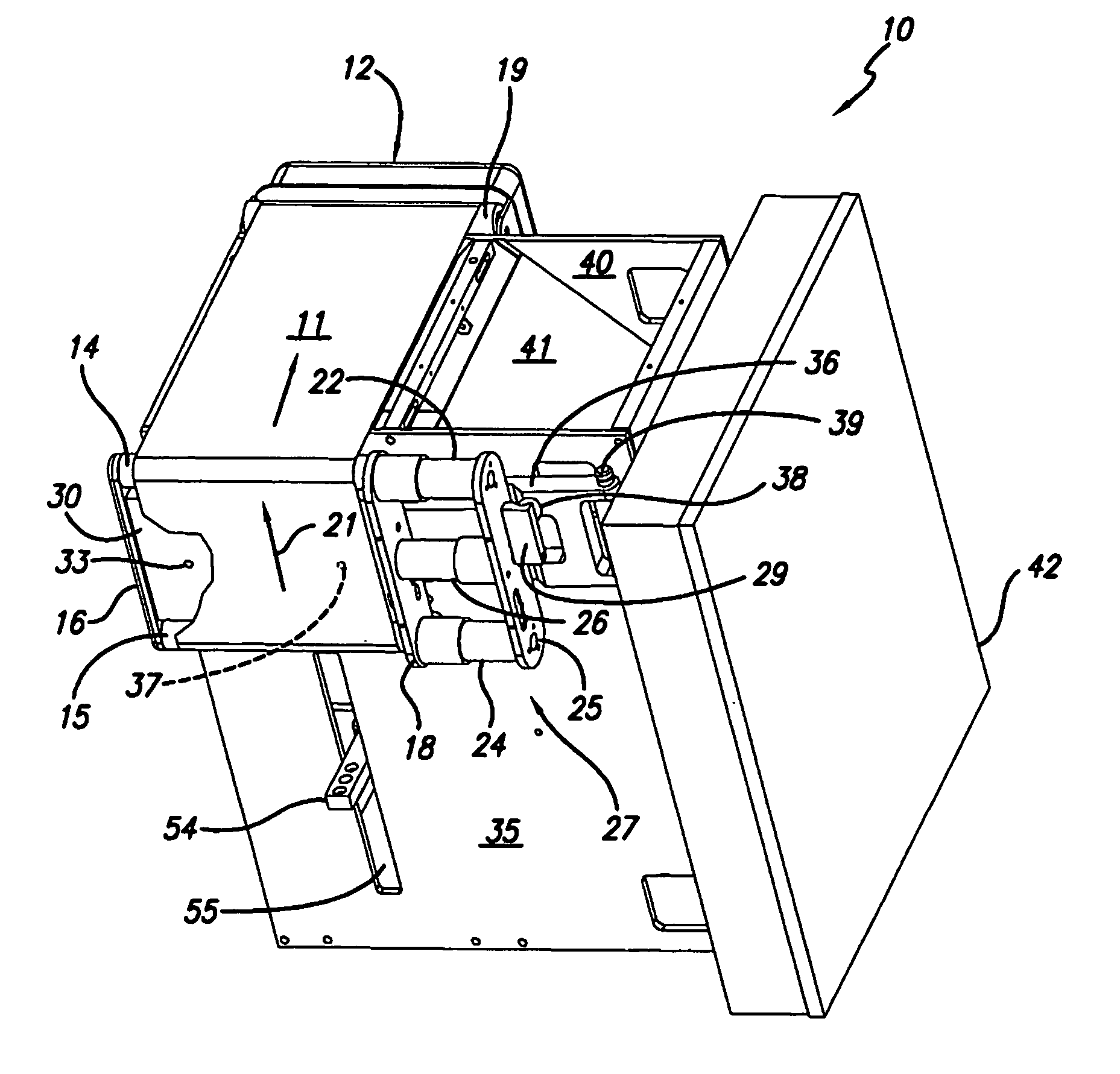
[0015] It is an advantage of the present invention that a low cost solid imaging device is obtained that provides accurate and repeatable layers of build material during the building of three-dimensional objects.
[0016] It is another advantage of the present invention that the belt tensioning material dispensing design is simple and effective in producing three-dimensional objects built layer-by-layer.
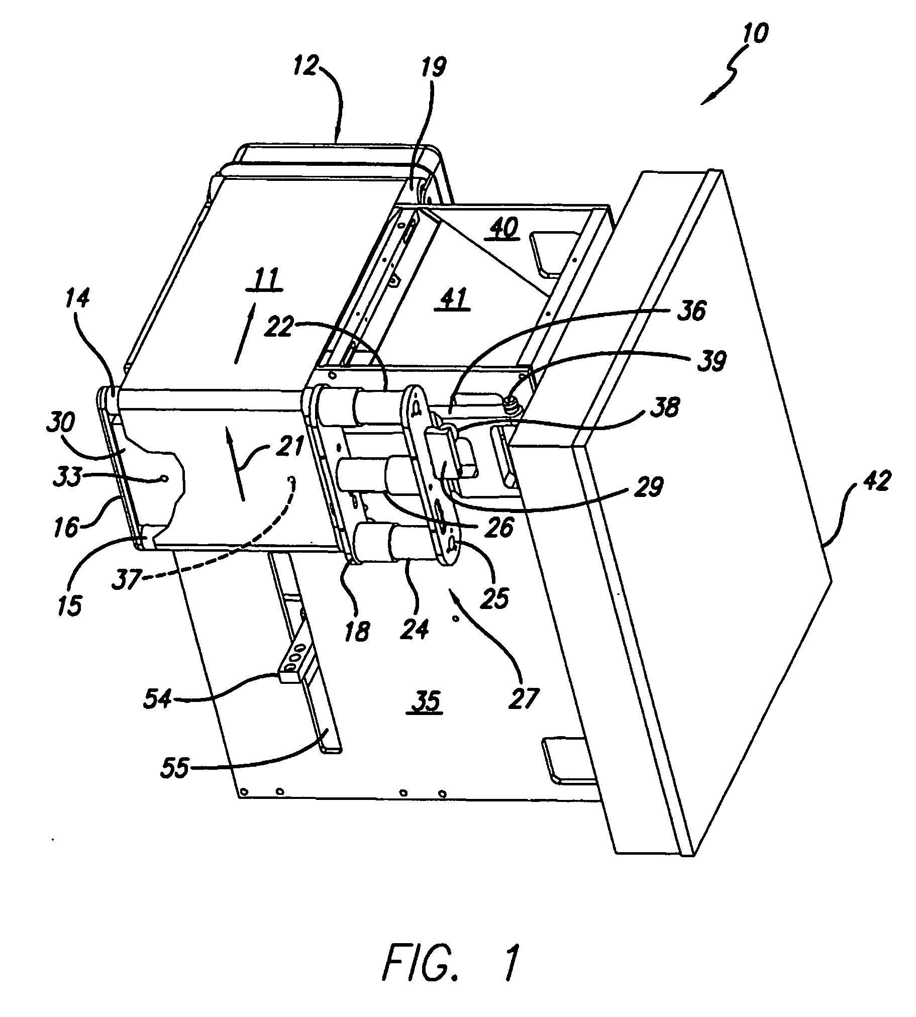
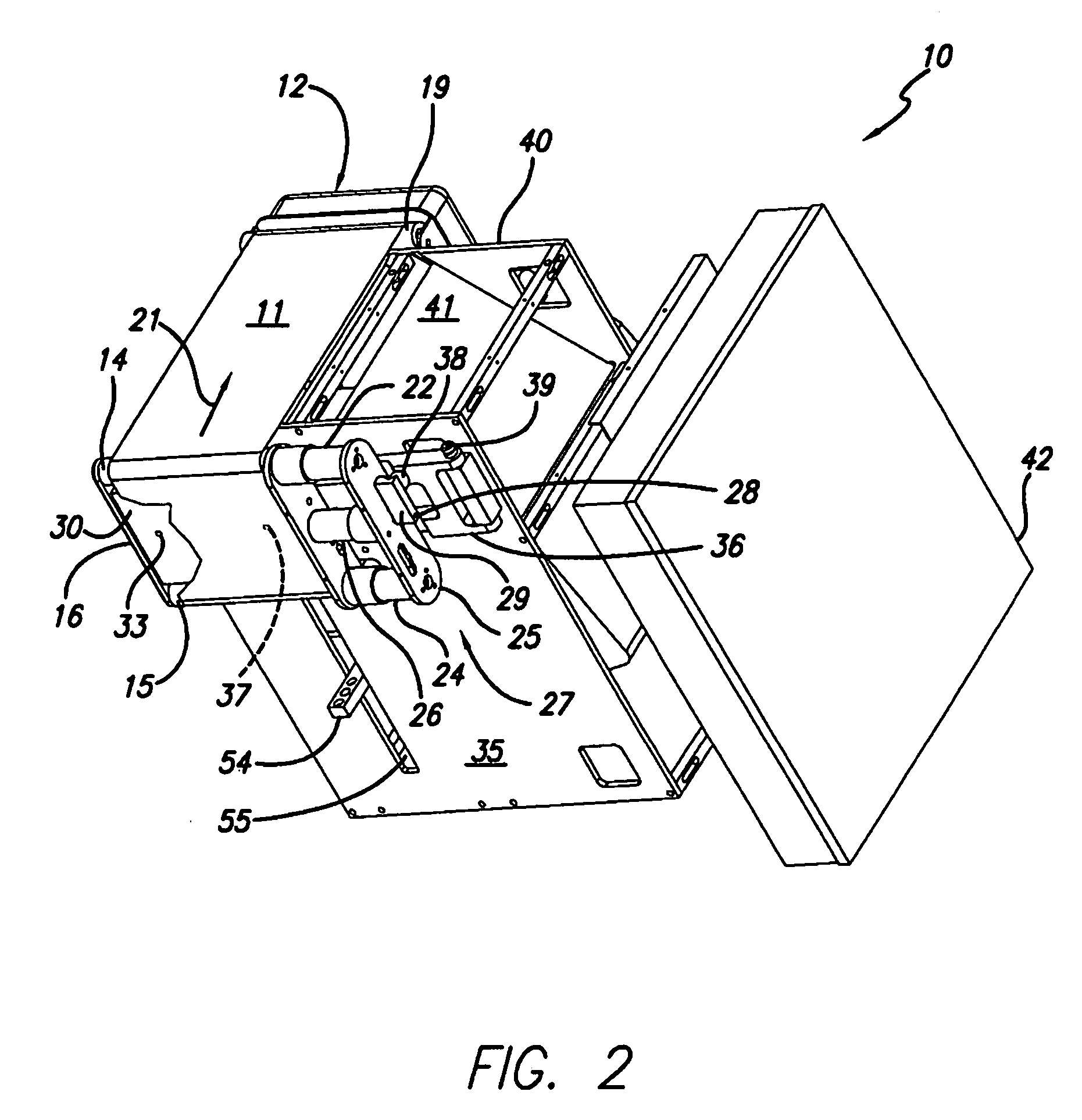
[0017] These and other aspects, features, and advantages are obtained by the present invention through the use of a solid imaging apparatus and method that employ an endless belt as a radiation transparent build material carrier and a belt tensioning system to control a fluid wedge formed at the dispenser to control the thickness of the layer of solidifiable liquid build material applied to the belt and transferred to a receiving substrate.

Problems solved by technology

Such systems have encountered and had to overcome difficulties relating to shrinkage, curl and other distortions, as well as resolution, accuracy, and difficulties in producing certain object shapes.
Voids caused by air pockets create discontinuities and weaknesses in the objects being built, as well as not accurately reproducing the three-dimensional aspect of the object being created from the CAD representation.
This problem is especially acute in technologies employing solidifiable liquid resin that is placed down layer-by-layer employing an intermediate transfer process.
Additionally, none of the prior solid freeform fabrication approaches, while making substantial improvements, have yet to achieve a truly low cost system that produces highly accurate and visually appealing three-dimensional objects in a short build time.

Method used


Image

  • Material delivery tension and tracking system for use in solid imaging
  • Material delivery tension and tracking system for use in solid imaging
  • Material delivery tension and tracking system for use in solid imaging

Examples


Embodiment Construction

[0026] Flexible transport solid imaging of the type disclosed herein involves employing an appropriate electro-optical radiation source in the layer-by-layer build-up of articles from a radiation curable liquid photopolymer material that is delivered by the flexible transport endless belt or reciprocatable sheet of film. The radiation source can employ any wavelength of radiation conducive to reflection from the electromagnetic spectrum, such as light valve technology with electron or particle beams, but preferably employs visible or UV radiation. Liquid photopolymer material is applied to the endless flexible belt or reciprocatable sheet of film from a cartridge employing an appropriate coating device, such as a gravure wheel or fluid wedge, that transfers the photopolymer build material to the flexible transport device to provide fresh material to create new layers as the three-dimensional object is built. The photopolymer build material is transferred via transfer means to a rece...


PUM

PropertyMeasurementUnit
Flexibilityaaaaaaaaaa
Transparencyaaaaaaaaaa
Distanceaaaaaaaaaa

Abstract

A solid imaging apparatus and method employing a radiation transparent build material carrier and a build material dispensing system that accurately controls the thickness of the transferred layer of solidifiable liquid build material to the radiation transparent build material carrier to achieve high resolution imaging in three-dimensional objects built using an electro-optical radiation source.

Description

FIELD OF INVENTION [0001] The present invention is directed to forming cross-sectional layers with an image projection system using a solidifiable build material in an apparatus for forming three-dimensional objects on a layer-by-layer basis. More particularly, it is directed to an apparatus and method for controlling the tension and tracking of an endless belt used to deliver in a desired thickness the solidifiable liquid build material used to form the three-dimensional object being built in response to exposure by UV or visible radiation. BACKGROUND OF THE INVENTION [0002] In recent years, many different techniques for the fast production of three-dimensional models have been developed for industrial use. These solid imaging techniques are sometimes referred to as rapid prototyping and manufacturing (“RP&M”) techniques. In general, rapid prototyping and manufacturing techniques build three-dimensional objects layer-by-layer from a working medium utilizing a sliced data set repres...

Claims


Application Information

Patent Timeline
IPC IPC(8): B29C35/08
CPCB29C67/0066B29C64/135B33Y10/00B33Y30/00
Inventor SPERRY, CHARLES R.MCNAMARA, DENNIS F.SCOTT, SUZANNE M.
Owner 3D SYST INC
Learn More