Device for delivery of stent for vessel

a technology for delivering a stent and a vessel, which is applied in the field of devices for delivering stents for vessels, can solve the problems of intimal hyperplasia, lack of therapeutic methods, and risk of blood vessel damage, and achieve the effects of easy torn, easy to be removed, and expanded diameter

Inactive Publication Date: 2007-11-08
IGAKI IRYO SEKKEI
View PDF4 Cites 83 Cited by
  • Summary
  • Abstract
  • Description
  • Claims
  • Application Information

AI Technical Summary

Benefits of technology

[0035] When the force is applied to the stent holding member, covering up the stent for the vessel, in a direction of enlarging the diameter of the stent holding member as a result of inflation of the balloon, the stent holding member is torn, with the tearing assisting portion of the distal end thereof as a guide, thereby releasing the holding of the stent for the vessel. Hence, the stent for the vessel may reliably be expanded in diameter, in keeping with the inflation of the balloon, at the same time as positive retention of the stent for the vessel is achieved on the balloon.
[0036] In particular, in the device for delivery of a stent for the

Problems solved by technology

Meanwhile, there lacks up to now a therapeutic method for such a case in which re-stenosis has occurred in a site where angioplasty has once been applied and where there has been implanted a metal stent.
On the other hand, if metal, inherently a foreign substance to the living body, is left in the living body for an extended per

Method used


Image

  • Device for delivery of stent for vessel
  • Device for delivery of stent for vessel
  • Device for delivery of stent for vessel

Examples


Embodiment Construction

[0054] In the following, a device for delivery of a stent for the vessel, according to the present invention, will be explained with reference to the drawings.

[0055] The device for delivery of a stent for the vessel, according to the present invention, is used for delivering the stent for the vessel, which is to be implanted in a vessel of a living body, such as blood vessel, trachea, bile duct or urethra, and which is used for supporting the inner lumen of the vessel, to a targeted site for implantation in the vessel.

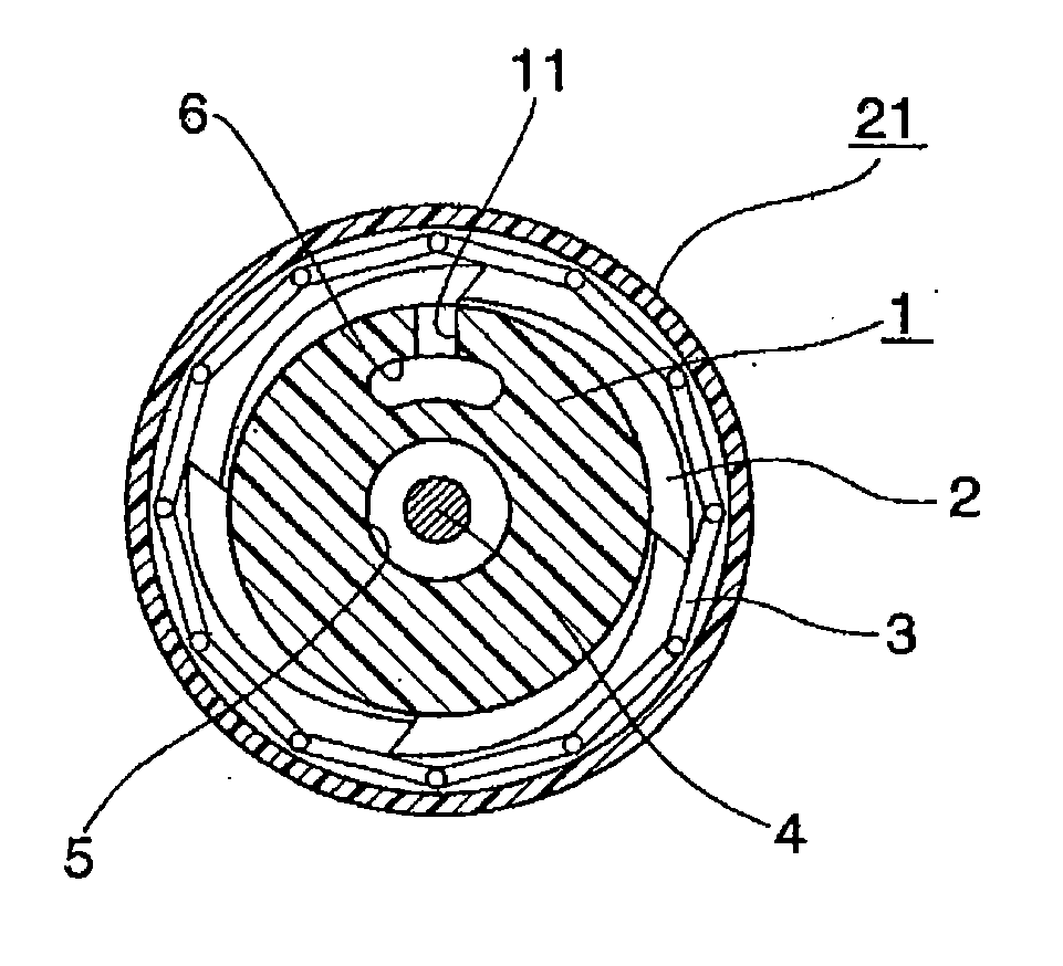
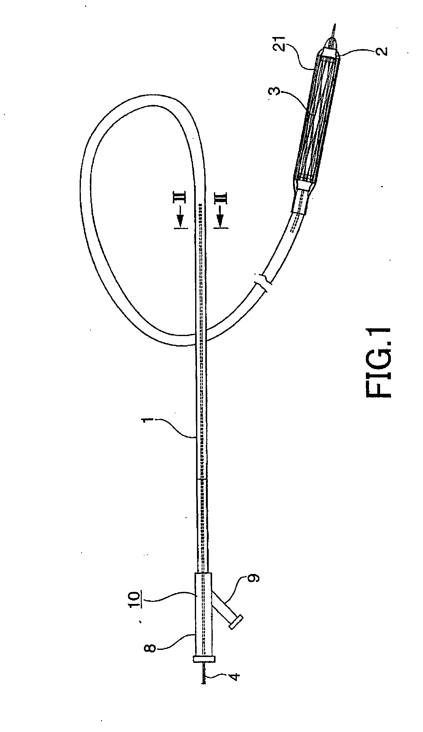
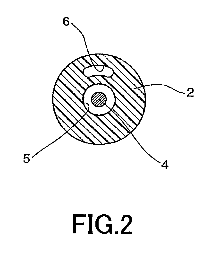
[0056] The device for delivery of a stent for the vessel, according to the present invention, includes a catheter 1, introduced into the vessel of a living body, and a balloon 2, adapted for being expanded by a fluid, supplied to the catheter 1, on the outer periphery of the distal end of the catheter, as shown in FIG. 1. On this balloon 2 is retained a stent for a vessel 3, which is implanted in the vessel of the living body, such as blood vessel, trachea, bile duct...


PUM


Abstract

A device for delivery of a stent for a vessel, used for implanting a stent for the vessel 3 in the vessel, is disclosed. The device for delivery of a stent for the vessel includes a catheter (1) for insertion into the vessel of a living body, a balloon (2) mounted on an outer peripheral surface of the distal end side of the catheter and inflatable with a fluid supplied to the catheter, a stent for the vessel (3), formed of a biodegradable polymer to a tube form, mounted on the balloon in a diameter-contracted state and having self-expanding properties, and a stent holding member (21) formed of a polymer material to a tube form for covering at least a portion of the stent for the vessel from the catheter for holding the stent for the vessel on the balloon. The stent holding member has been drawn in the longitudinal direction. In the distal end of the stent holding member, located towards the distal end of the catheter, there is formed a tearing assisting portion (22). The stent holding member is torn along the tearing assisting portion, by expansion of the stent for the vessel attendant on inflation of the balloon, to release its holding of the stent for the vessel to enable expansion of the stent for the vessel (3).

Description

TECHNICAL FIELD [0001] This invention relates to a device for delivery of a stent for a vessel, in which a stent for a vessel of a living body, such as blood vessel, trachea, bile duct or urethra, implanted in the vessel of the living body to support the inner lumen of the vessel from the inside, is held on a balloon provided to a catheter inserted into the vessel of the living body. More particularly, this invention relates to a device for delivery of a stent for the vessel, in which the stent for the vessel may be delivered to a targeted site of implantation in the vessel as the stent for the vessel is maintained mounted on the balloon provided to the catheter. [0002] The present application claims priority based on the Japanese Patent Application 2003-355358 filed in Japan on Oct. 15, 2003, the entire contents of which are incorporated herein by reference. BACKGROUND ART [0003] Where the state of stenosis has occurred in the vessel of a living body, such as a blood vessel of a li...

Claims


Application Information

Patent Timeline
IPC IPC(8): A61F2/84A61F2/06A61M29/00
CPCA61F2/95A61F2002/9583A61F2/97A61F2/958
Inventor IGAKI, KEIJI
Owner IGAKI IRYO SEKKEI
Why Eureka
Try Eureka