
Vehicle Drive Control System and Sensor Unit and Tire

Inactive Publication Date: 2007-11-08
YOKOHAMA RUBBER CO LTD
View PDF2 Cites 19 Cited by
  • Summary
  • Abstract
  • Description
  • Claims
  • Application Information

AI Technical Summary

Benefits of technology

[0033] Also, according to the present invention, in the above vehicle drive control system, in order to improve the accuracy of sensing a tire ground contact pattern, the sensor section is configured to sense accelerations in different directions at one given position.
[0037] Since two or more filters are used in this manner, a shift in phase produced according to signal frequency when passing through the filter can be reduced.
[0039] Since two or more filters are used in this manner, a shift in phase produced according to signal frequency when passing through the filter can be reduced.
[0044] The vehicle drive control system of the present invention allows proper control during running of the vehicle, thus improving stability during running. Also, tire distortion quantity, vehicle skid, wheelspin, tire grip and the like can be estimated from the accelerations. Accordingly, when these are used for vehicle brake control, the control can be performed with higher accuracy.
[0045] According to the sensor unit of the present invention, to make it possible to highly accurately and easily sense the information required for the above system, it is sufficient to mount the unit in a predetermined position of the tire.
[0046] According to the tire of the present invention, since the above sensor unit is provided, the information required for the above system can be highly accurately and easily sensed.

Problems solved by technology

According to conventional art, when the friction force between the road surface and a tire is reduced in such cases as when the road surface is wet in the rain, the vehicle can skid and move in an unexpected direction at the time when the accelerator is pushed down, causing an accident.
In the technique disclosed in Patent Document 1, however, while the brake control operation feeling is improved, when the friction force between the tire and road surface changes, it is difficult to set a threshold value for which there are assumed such cases as when the brake torque exceeds the friction force between the tire and road surface, thus causing a skid.
Consequently, even with the control method which takes into consideration the acceleration of the vehicle itself during its running, highly accurate control may be impossible.

Method used


Image

  • Vehicle Drive Control System and Sensor Unit and Tire
  • Vehicle Drive Control System and Sensor Unit and Tire
  • Vehicle Drive Control System and Sensor Unit and Tire

Examples


Embodiment Construction

[0080] One embodiment of the present invention will be described below with respect to the drawings.

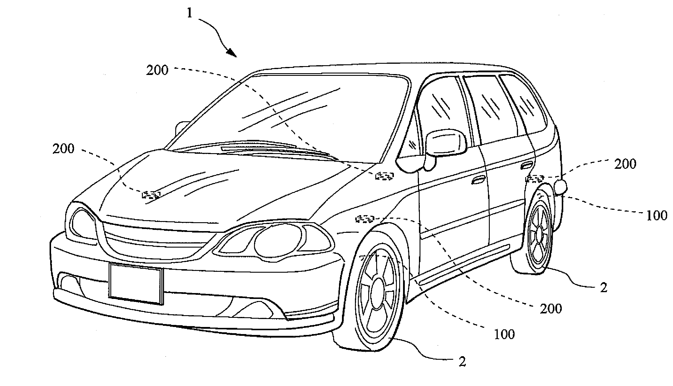
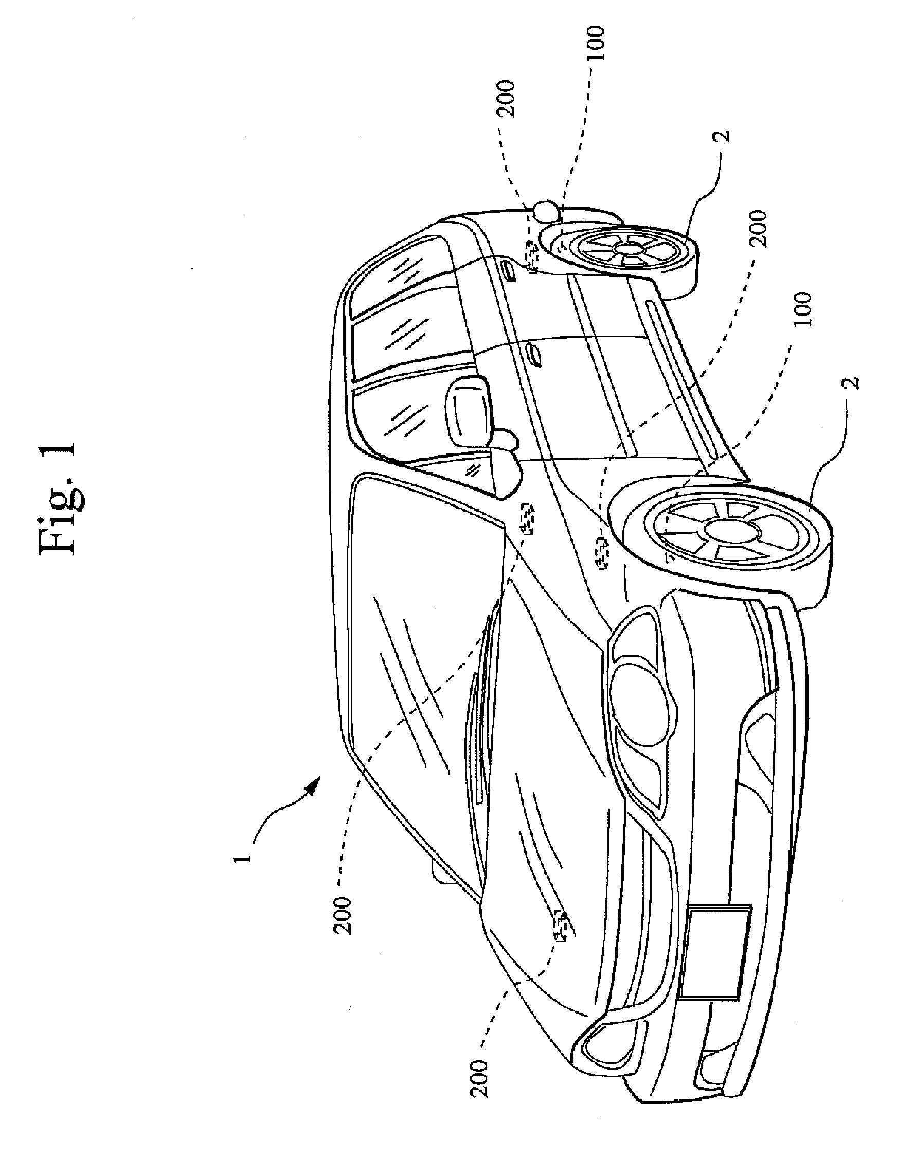
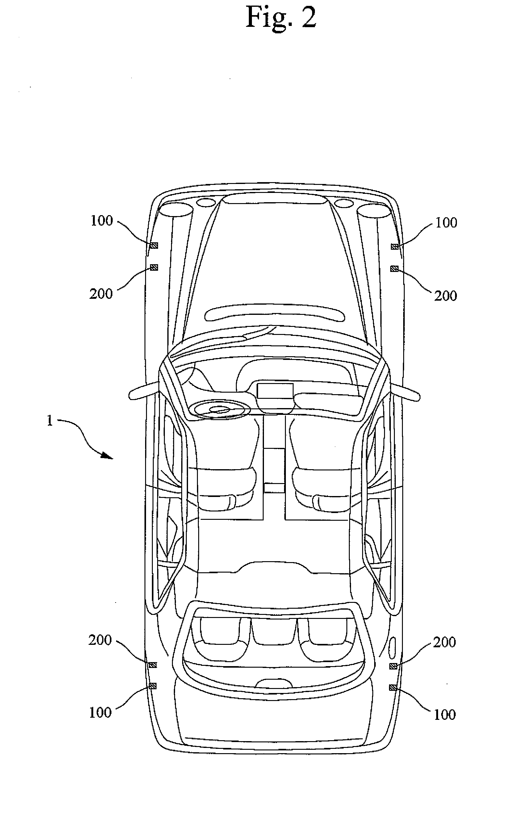
[0081]FIG. 1 is an external view showing the arrangement of a monitor device and sensor unit according to one embodiment of the present invention. FIG. 2 is a plan view showing the arrangement of a monitor device and sensor unit according to one embodiment of the present invention. FIG. 3 is a view for explaining the location of placement of the sensor unit in a tire according to the one embodiment of the present invention. FIG. 4 is a view showing a tire inside a tire house according to the one embodiment of the present invention. FIG. 5 is a configuration diagram showing a vehicle drive control system according to the one embodiment of the present invention. In the present embodiment, a four-wheel vehicle drive control system is described by means of an example.

[0082] In FIGS. 1 and 2, reference numeral 1 denotes a vehicle, 2 denotes a tire (wheel), 100 denotes a sensor unit, and ...


PUM


Abstract

There is provided a vehicle drive control system performing the stability control of a vehicle by highly accurately and easily sensing accelerations generated in each tire and sensing a tire ground contact pattern, a sensor unit thereof and a tire. Using a sensor unit 100 mounted in each tire 2 of a vehicle 1, accelerations generated in X, Y and Z directions are sensed and at the same time, a low frequency noise component and high frequency noise component added to the Z axis direction acceleration signal are extracted. Digital values being the sensing result are transmitted as digital information to a monitor device 200 by radio wave. The monitor device 200 compares many pieces of tire ground contact pattern information preliminarily stored with the digital information to thereby specify a tire ground contact pattern and output the information to a stability control unit 700. The stability control unit 700 performs, based on the acceleration values and the information on tire ground contact pattern obtained, the correction control of driving of a sub-throttle actuator 412 or a brake drive actuator 640.

Description

TECHNICAL FIELD [0001] The present invention relates to a vehicle drive control system performing the stability control of a vehicle body during running of the vehicle, and a sensor unit thereof and a tire. BACKGROUND ART [0002] According to conventional art, when the friction force between the road surface and a tire is reduced in such cases as when the road surface is wet in the rain, the vehicle can skid and move in an unexpected direction at the time when the accelerator is pushed down, causing an accident. [0003] To prevent an accident caused by such skids, sudden acceleration, and soon, there have been developed Anti-Lock Brake System (hereinafter referred to as ABS), Traction Control System, and further a stability control system provided with a YAW sensor, and other systems. [0004] For example, ABS is a system which senses the rotation state of each tire and controls the braking force based on the sensing result to prevent each tire from entering a locking state. [0005] As t...

Claims


Application Information

Patent Timeline
IPC IPC(8): G06F7/00B60T8/1755B60T8/1761B60W30/00B60W30/02B60W40/068B60W40/10F02D29/02F02D41/04
CPCB60C23/064B60G2204/113B60G2400/64B60G2800/182B60G2800/22B60G2800/94B60W2530/20B60W10/06B60W10/18B60W10/20B60W30/02B60W40/101B60T8/1725
Inventor HATTORI, YUTAKA
Owner YOKOHAMA RUBBER CO LTD
Learn More