Process for producing leaves for leaf seal

Inactive Publication Date: 2007-11-15
ANSALDO ENERGIA IP UK LTD
View PDF10 Cites 14 Cited by
  • Summary
  • Abstract
  • Description
  • Claims
  • Application Information

AI Technical Summary

Benefits of technology

[0021] One aspect of the present invention includes a process for producing leaves with an integral spacer element for a leaf seal for rotary machines, in particular

Problems solved by technology

However, they offer the advantage of low rotary friction, and consequently a virtually unlimited service life.
Brush seals, on the other hand, have higher friction losses on account of the friction between the ends of the bristles and the rotor shaft.
This leads to wear, which limits the service life of the seal.
There are numerous restrictions on the use of these technologies for sealing purposes in gas turbines.
First, the axial pressure difference which they are able to withstand is still rather low.
In the case of brush seals, this is because of the bristles, which have the same rigidity in the axial and circumferential directions: high pressures can cause the bristles to blow back onto themselves in the axial direction.
The seals also have little abil

Method used


Image

  • Process for producing leaves for leaf seal
  • Process for producing leaves for leaf seal
  • Process for producing leaves for leaf seal

Examples


Embodiment Construction

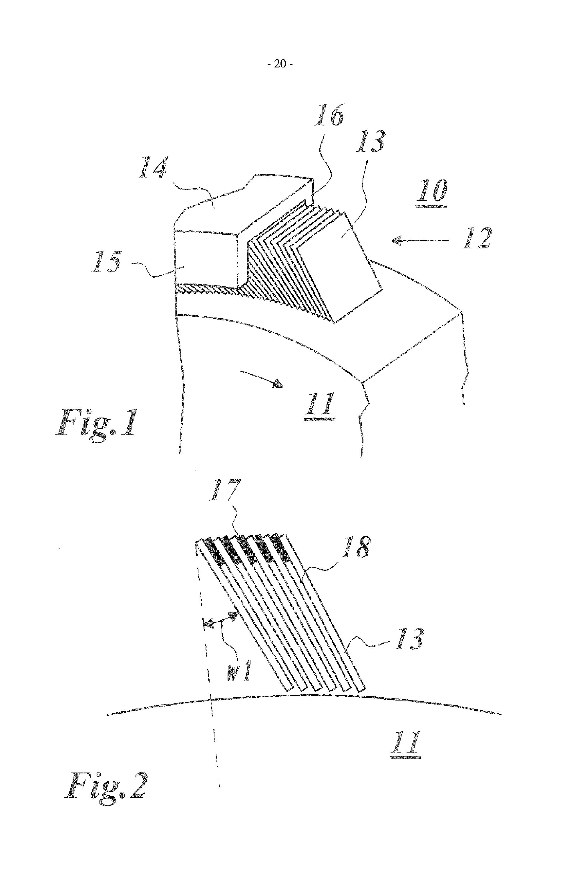
[0042]FIG. 1 shows a perspective side view of the typical structure of a leaf seal as used in a gas turbine. The leaf seal 12 seals a rotor shaft 11, which rotates in the direction indicated by an arrow, of the gas turbine 10 with respect to a housing 14. In the annular space between the rotor shaft 11 and the housing 14, a set of thin leaves 13, which are spaced apart from one another at narrow intervals, is arranged in a ring. The surface of the leaves 13 is oriented parallel to the axis of rotation of the machine. In accordance with FIG. 2, the leaves are tilted out of the radial direction through an angle w1 and between them in each case have a narrow gap or space 18, which is preferably defined by spacer elements 17 arranged between the leaves 13. The spacer elements 17 shown in FIG. 2 are illustrated as separate elements. However, they may also be integrated in the leaves.

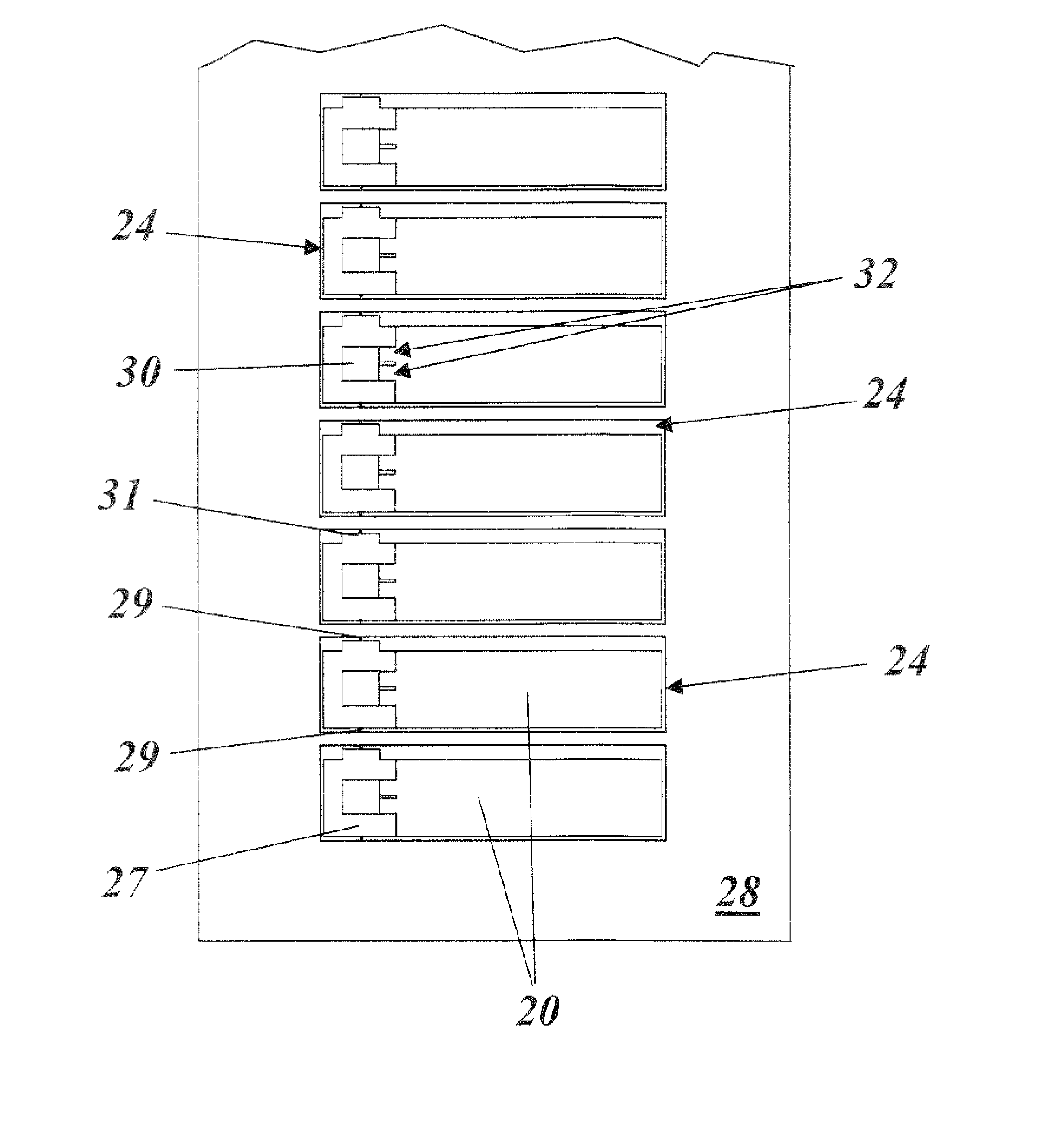
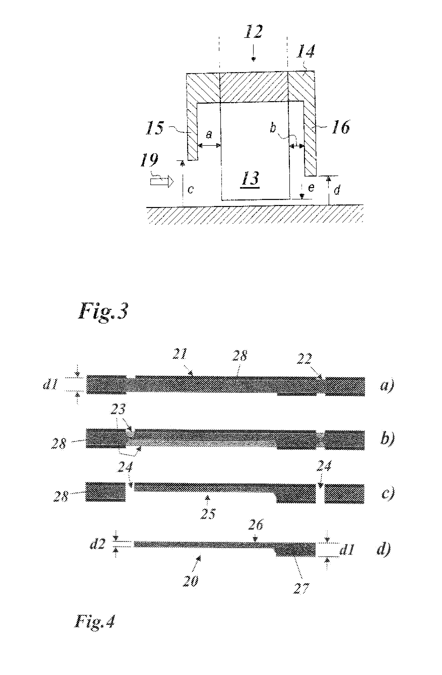
[0043] In accordance with FIG. 1 and 3, the air flow through the leaves 13 can be altered by using a fron...


PUM

PropertyMeasurementUnit
Thicknessaaaaaaaaaa
Coefficient of linear thermal expansionaaaaaaaaaa

Abstract

In a process for producing leaves (20, 20′) for a leaf seal, in particular as a seal for a gas turbine, which leaves (20, 20′) are laterally delimited by a peripheral edge contour and have regions of different thicknesses (d1, d2), a simplification, without sacrificing precision, is achieved by virtue of the edge contour of the leaves (20, 20′) being cut out of a metal sheet (28) by an etching process and the regions of different thicknesses (d1, d2) also being produced simultaneously as part of the etching process.

Description

[0001] This application is a Continuation of, and claims priority under 35 U.S.C. §120 to, International application number PCT / EP2005 / 051735, filed 20 Apr. 2005, and claims priority therethrough under 35 U.S.C. §119 to Great Britain application no. 0409247.4, filed 26 Apr. 2004, the entireties of which are incorporated by reference herein. BACKGROUND OF THE INVENTION [0002] 1. Field of the Invention [0003] The present invention deals with the field of seals for rotary machines and to a process for producing leaves for a leaf seal. [0004] 2. Brief Description of the Related Art [0005] A gas turbine includes a rotor, on which there are arranged various stages having compressor blades and turbine blades, as well as a stator housing. The rotor is mounted in bearings at each end of the rotor shaft. [0006] Control of the gas flow within the gas turbine is of great importance both with regard to the functionality and with regard to the efficiency. At various points along the rotor shaft, ...

Claims


Application Information

Patent Timeline
IPC IPC(8): B23P25/00B23P13/04F16J15/32
CPCF16J15/3292Y10T29/49297Y10T29/49995Y10T29/49885
Inventor HOGG, SIMON IANRHODES, NIGEL ANTHONYSCHOENFELD, ERWIN
Owner ANSALDO ENERGIA IP UK LTD
Why Eureka
Try Eureka