[0009] It is an object of the present invention to minimize
energy loss and increase refueling efficiency in
hydrogen refilling systems when factored into the overall energy efficiency of an infrastructure of
high pressure gas powered vehicles and fuel depots for the
consumer dispensation of high pressure fuel. Typically, each time a vehicle is refueled with
hydrogen, mechanical compression transforms into
thermal energy and results in the heating of refueled gas in the tank, hence, it is an object of the invention to minimize tank heating and to increase the efficiency and refueling capacity of an
on board fuel storage tank in a hydrogen powered motor vehicle. It is an object of the invention to minimize
high pressure gas tank heating and to increase the efficiency and refueling capacity of an
on board fuel storage tank in
high pressure gas powered motor vehicles. It is an object of the invention to provide a
system that can remove the compression heat resulting from refueling an
on board tank during high pressure refueling. An avoidance of secondary
gas cooling pretreatment and / or pressure overfill, a speedier refueling time, increased refueling efficiency, and an extension of overall vehicle range will result. Improved tank capacity per
unit volume is achieved during refilling, particularly where nominal refill pressure is in the range of about 10,000 psi or greater for hydrogen and about 3,600 psi for CNG. SUMMARY OF THE INVENTION
[0010] The invention provides a system that can remove the heat of compression resulting from the high pressure refueling of an on board vehicle tank. Refueling time will decrease and refueling efficiency and overall vehicle range will increase as a result of the improved tank capacity per
unit volume achieved by the tank
gas cooling system described herein. In accordance with the present invention, effective reduction of
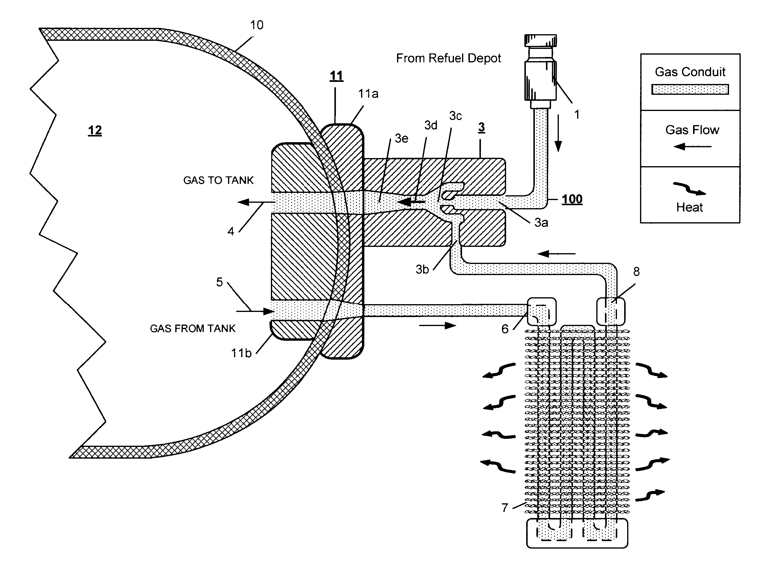
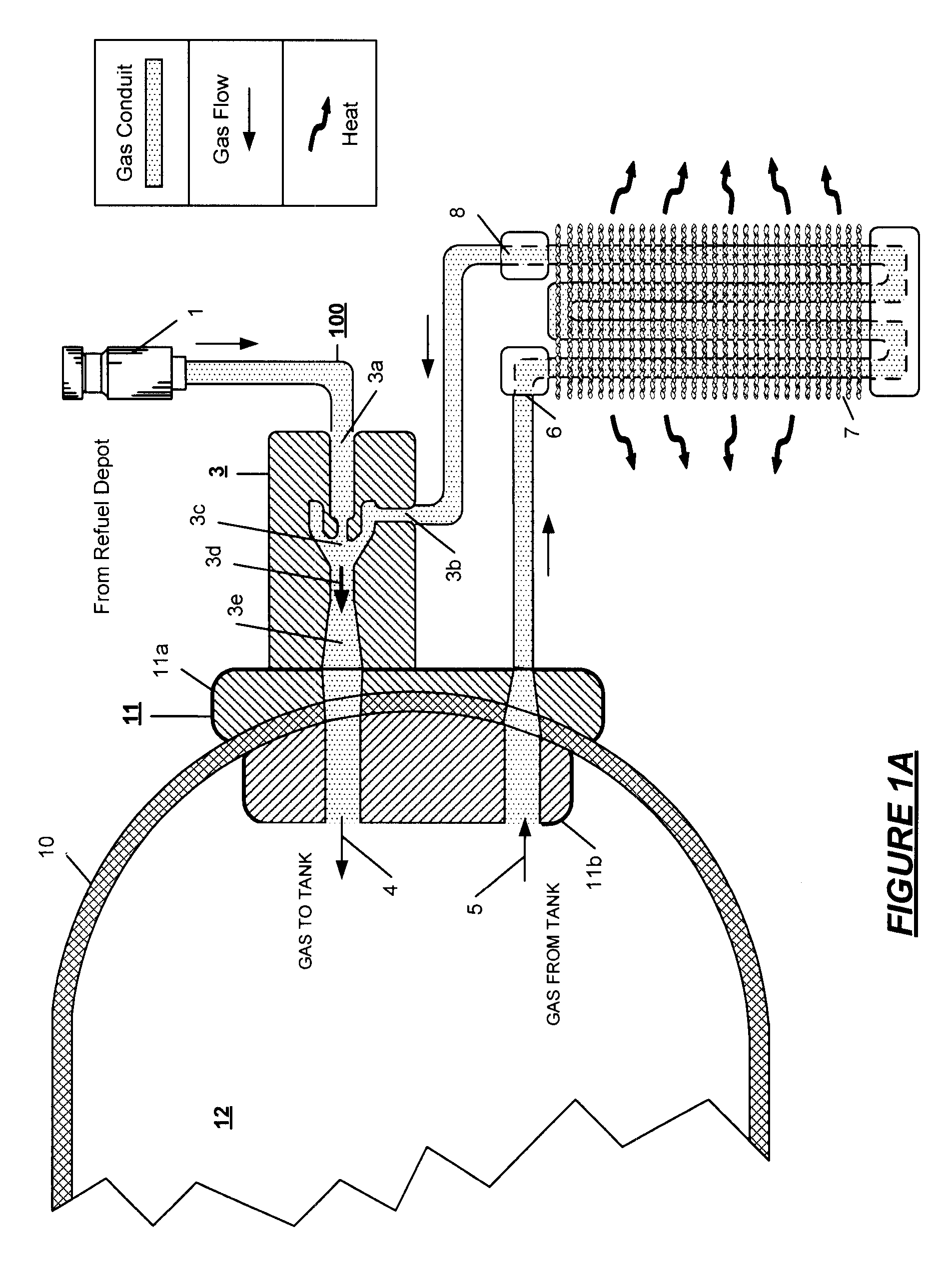
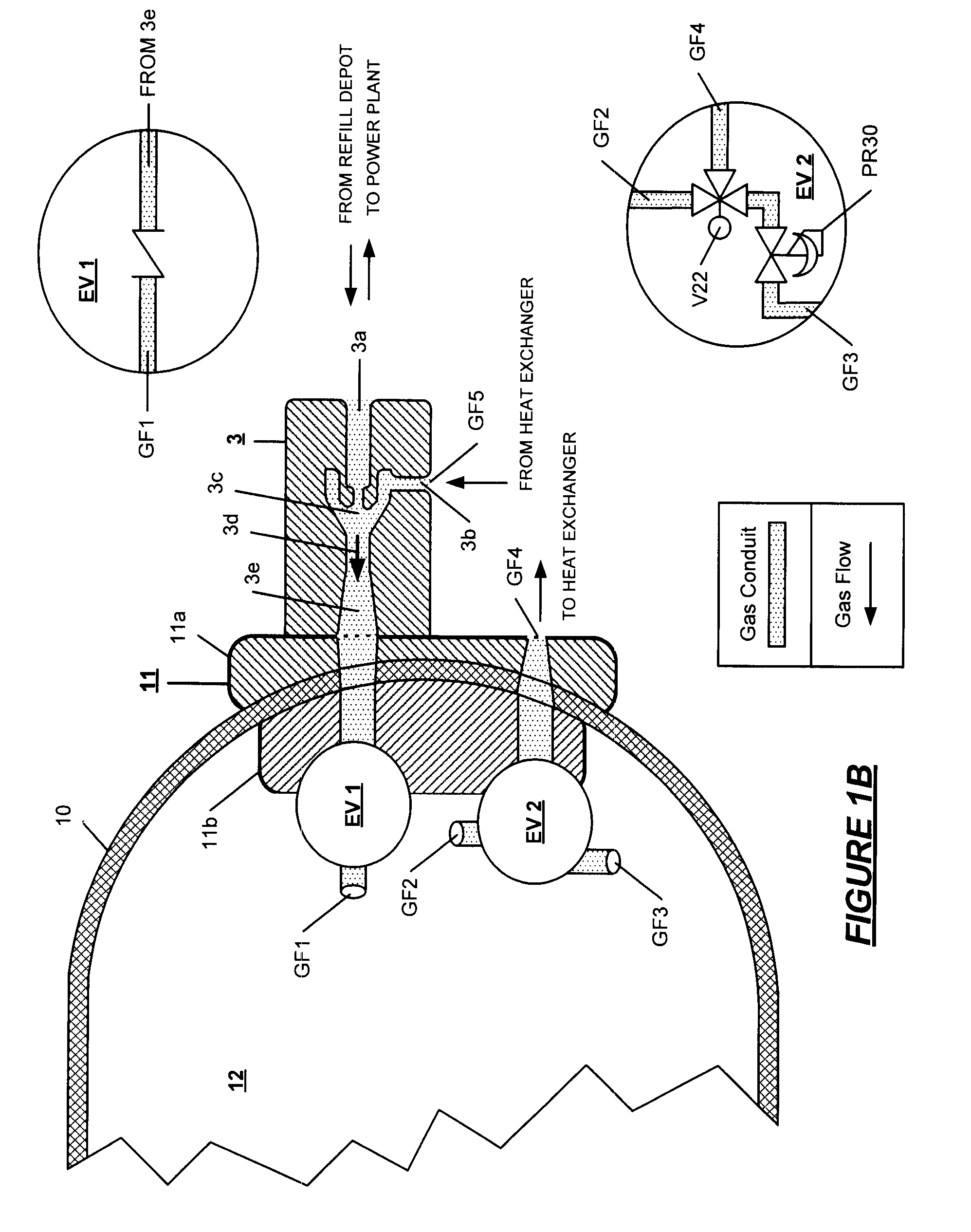
fuel tank heating during the refueling process is provided by introducing the refueling gas into an ejector pump that sucks out the hot gas from within the tank and in a circuit introduces the hot gas into a heat exchanger where the gas is then cooled down. The cooled gas and the refueling gas are mixed in the ejector and then both gas streams are directed into the vehicle
storage tank.
[0011] The system described herein provides onboard cooling; as a result, there is no need to change the refueling
station equipment. The cost and weight of on board
gas cooling equipment, important factors in the adoption of high pressure fueled vehicles, are reduced; there is no internal heat exchanger in the confines of the tank.
Cooling capacity is improved; continuous cooling is provided. Heat exchange efficiency approaches 100%. When there is an internal heat exchanger, the gas temperature in the heat exchanger is not perfectly equal to tank gas temperature, thus reducing internal heat exchanger efficiency to less than 100%. In the gas ejector system described herein, the gas flow cooling circuit is interconnected with an external heat radiator, thereby collecting interior tank heat and radiating the absorbed heat into the ambient
atmosphere or other system appropriate for the use,
radiation, absorption, or disposal of the collected heat of high pressure refueling.
[0012] In brief, the invention provides a system for reducing the energy and for reducing the time required to refill on board tanks on a vehicle from a high pressure fuel depot refilling line operatively interconnected to the tank wherein the refilling gas itself is circulated within the on board tank to absorb the compression heat of refueling, and the heat thereby absorbed, is radiated from the cooling circuit to an external environment before the fuel reaches the tank such that a close to optimum refill of the tank is achieved.
[0013] It is an object of the invention to provide a gas jet ejector wherein a Venturi pump utilizes the energy in the high pressure gas to create a lower pressure that can entrain another gas
stream. A gas jet ejector has no
moving parts and requires no maintenance thereby providing a distinct
advantage over mechanical pumps. Reliability is achieved in that once the motive pressure is set, the ejector performance is maintained over a range of operating conditions. Shutdown and restart are possible without complication. The pump connections,
nozzle inlet, suction inlet and
throat outlet, provide the jet (Venturi) pump that is conveniently adaptable to a high pressure environment.

