
Flat gasket, in particular, cylinder head gasket

a flat gasket and cylinder head technology, applied in the direction of engine sealing, metal-working apparatus, sealing arrangement of engines, etc., can solve the problems of sheet metal then prone to tear when being folded, and the width of thickened zones can only be produced with a slight width

Inactive Publication Date: 2007-11-15
ELRINGKLINGER AG
View PDF7 Cites 13 Cited by
  • Summary
  • Abstract
  • Description
  • Claims
  • Application Information

AI Technical Summary

Benefits of technology

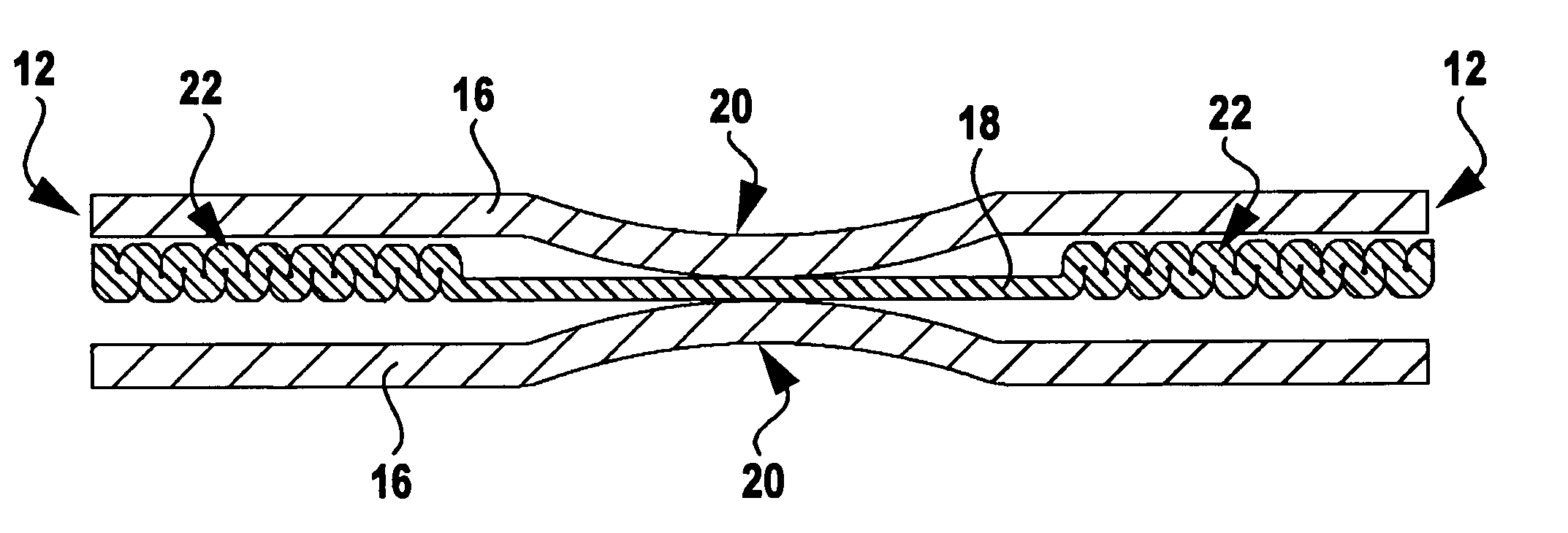
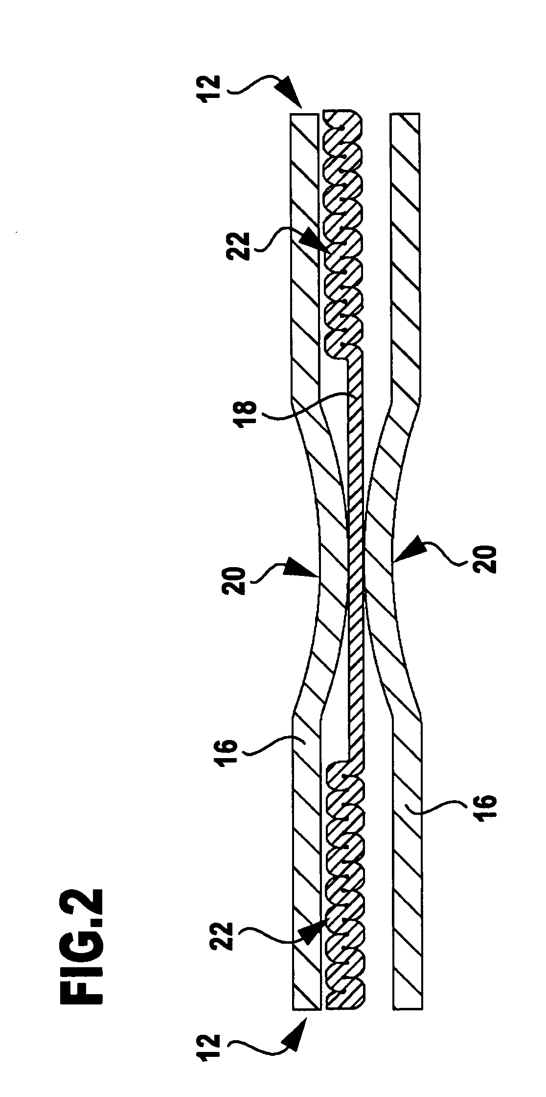
[0009] Since such an arch as well as conventional, stamped beads can be readily produced in the desired height, several such arches can also be produced without any difficulty immediately adjacent to one another, and the arch or several arches lying adjacent to one another can be strongly compressed by a suitable pressing tool perpendicularly and / or parallel to the plane of the layers, the invention makes it possible to produce a supporting element with a prescribed desired height and / or width by simple reshaping techniques, which is otherwise only possible with separately produced supporting elements that are welded onto or attached in some other way to a sheet metal layer.
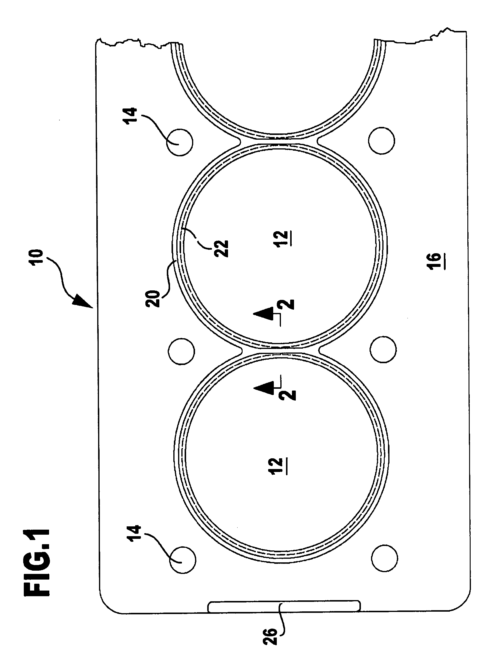
[0020] In particular, when the flat gasket according to the invention is a cylinder head gasket, it may be advantageous for the second sheet metal layer provided with the supporting element or with supporting elements to be arranged between two first sheet metal layers provided with sealing beads. A supporting element or supporting elements can then form one or more stoppers to protect sealing beads of the two first sheet metal layers from excessive deformations.
[0023] As will be apparent from the foregoing, the invention also relates to a method for the manufacture of a flat gasket according to the invention, wherein a sheet metal layer consisting of a sufficiently ductile steel, in order to produce the supporting element in an edge area of this sheet metal layer that is delimited by a free edge, is fixed near to and along this edge area, and the at least one arch is stamped into the sheet metal layer in such a way that the free edge is drawn in the direction towards the fixed area of the sheet metal layer. Therefore, with this type of manufacture, the material required for stamping the arch is drawn from the free edge of the sheet metal layer into the area to be reshaped, so that the sheet thickness in the area of the arch is at least not substantially reduced by the stamping of the arch.

Problems solved by technology

Furthermore, in this known cylinder head gasket the thickness of a thickened zone must as a consequence always be a multiple of the sheet thickness, and, in addition, these thickened zones can only be produced with a slight width because the sheet metal would otherwise tear when being folded over.
It is also problematic to produce at an edge area of the sheet metal layer, which in a plan view is round, a supporting element which extends from the edge of the cylinder head gasket over quite a large extent into the interior of the gasket because, as described hereinabove, the sheet metal then tends to tear when being folded over.

Method used


Image

  • Flat gasket, in particular, cylinder head gasket
  • Flat gasket, in particular, cylinder head gasket
  • Flat gasket, in particular, cylinder head gasket

Examples


second embodiment

[0039] In this second embodiment, too, the free edge 32′ of the edge area 34′ shifts towards the left in accordance with the drawings during the stamping procedure represented in FIG. 4A.

third embodiment

[0040] In the third embodiment shown in FIGS. 5A to 5D, a bead-like arch 44″ is stamped into an edge area 34″ of a sheet metal layer 30″ again fixed between two clamping jaws 36″ and 38″, using a stamping tool comprising an upper tool portion 40″ and a lower tool portion 42″. The edge area 34″ is then compressed and reshaped in a multi-part stamping tool shown in FIG. 5B. This stamping tool has an upper stamp die 54a″, a lower stamp die 54b″, a press die 54c″ and an abutment die 54d″. The directions of movement of these tool portions are indicated by arrows in FIG. 5B. The edge area 34″ is compressed not only perpendicularly to the plane of the sheet metal layer 30″ but also in horizontal direction in accordance with the drawings by the inclined faces on the left side of the abutment die 54d″ in accordance with the drawings and by the press die 54c″. A cross-sectional profile of the edge area 34″ thus results, which in the technical terminology of the structural designer of metallic...


PUM

PropertyMeasurementUnit
Timeaaaaaaaaaa
Pressureaaaaaaaaaa
Electrical resistanceaaaaaaaaaa

Abstract

Flat gasket comprising a first sheet metal layer consisting of a spring steel and a second sheet metal layer consisting of a ductile steel, the first layer being provided with a sealing bead, and the second layer being provided in an edge area bordering on an edge of the layer with a thickened zone as supporting element for receiving pressing forces; to increase the design possibilities for such a supporting element, the latter is formed by at least one elongate arch of the second layer, which is stamped into the edge area of the second layer and extends approximately parallel to the free edge of the edge area, the arch being compressed in such a way that the metal volume of the supporting element is at least three times the total hollow space volume which the supporting element and two tangential planes abutting on the latter and extending parallel to the plane of the second layer include between them.

Description

[0001] The present disclosure relates to the subject matter disclosed in German application number 10 2006 021 499 of May 9, 2006, which is incorporated herein by reference in its entirety and for all purposes. BACKGROUND OF THE INVENTION [0002] The invention relates to an at least substantially metallic flat gasket comprising at least one first sheet metal layer consisting of a spring steel and at least one second sheet metal layer consisting of a ductile steel, the first layer being provided with at least one sealing bead, and the second layer being provided in at least one edge area bordering on a free, peripheral or an inner edge of the sheet metal layer with at least one thickened zone as supporting element for receiving pressing forces acting on the flat gasket when the latter is installed. [0003] In particular, the invention relates to such a flat gasket as is designed as cylinder head gasket, and in the following the invention will be explained with reference to cylinder hea...

Claims


Application Information

Patent Timeline
IPC IPC(8): F02F11/00
CPCF16J15/0825Y10T29/49906Y10T29/49297F16J2015/085
Inventor WERZ, ULRICHGRUHLER, TOBIASSCHENK, PETERFRITZ, WOLFGANGBRODBECK, WILLIBAUR, MATTHIAS
Owner ELRINGKLINGER AG
Learn More