Exposure device and image forming apparatus

Inactive Publication Date: 2007-11-15
KYOCERA DOCUMENT SOLUTIONS INC
View PDF7 Cites 11 Cited by
  • Summary
  • Abstract
  • Description
  • Claims
  • Application Information

AI Technical Summary

Benefits of technology

[0008]An object of the present invention is to provide an exposure device and a light scanning unit having simple constructions and capable

Problems solved by technology

Since the polygon motor and the polygon mirror rotate at high speeds in the LSU as described above, noise and heat are generated.
The noise leads to the deterioration of a workplace environment, whereas the heat generation causes the nonuniform rotation of the polygon mirror and distortions in optical devices such as lenses, thereby causing an exposure failure.
Howe

Method used


Image

  • Exposure device and image forming apparatus
  • Exposure device and image forming apparatus
  • Exposure device and image forming apparatus

Examples


Embodiment Construction

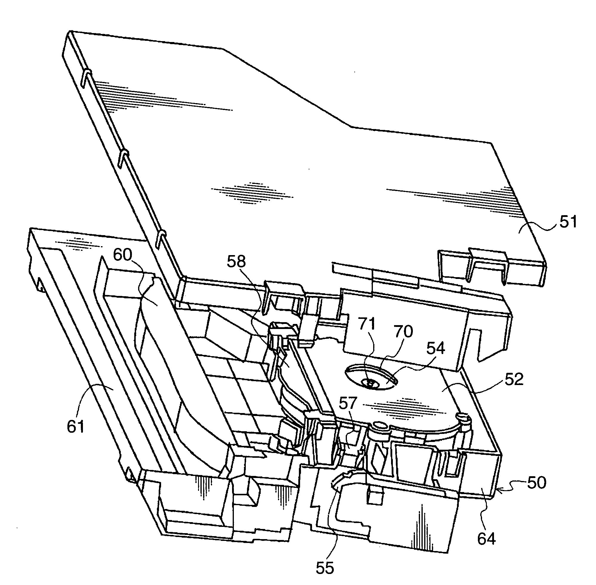
[0023]Hereinafter, best modes of the present invention are described in detail with reference to the accompanying drawings. It should be noted that members and the like identified by the same reference numerals have the same constructions in the respective drawings and the repetitive description of these is suitably left out, and that the diagrammatic representation of members and the like unnecessary for the description is suitably left out.

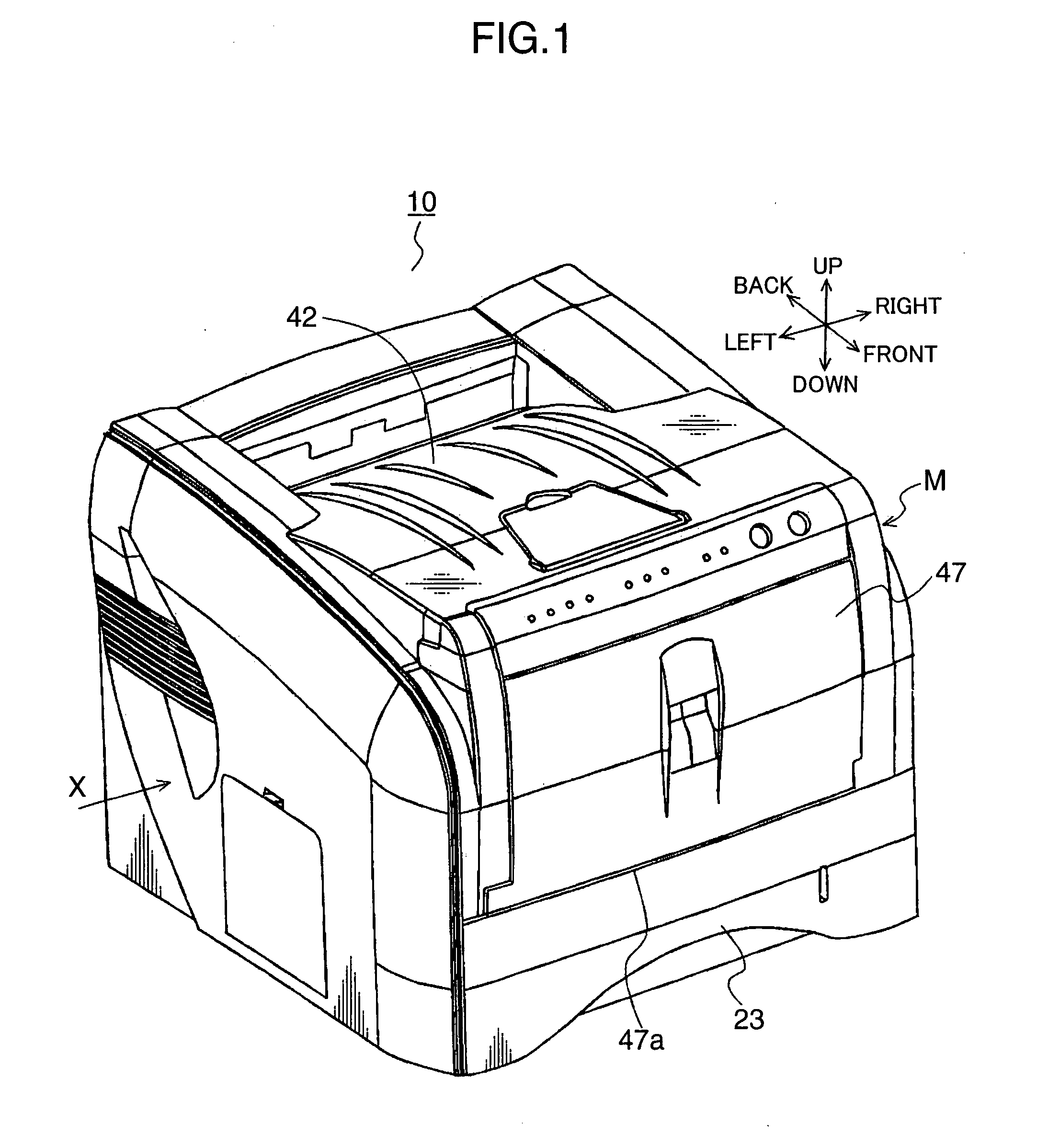
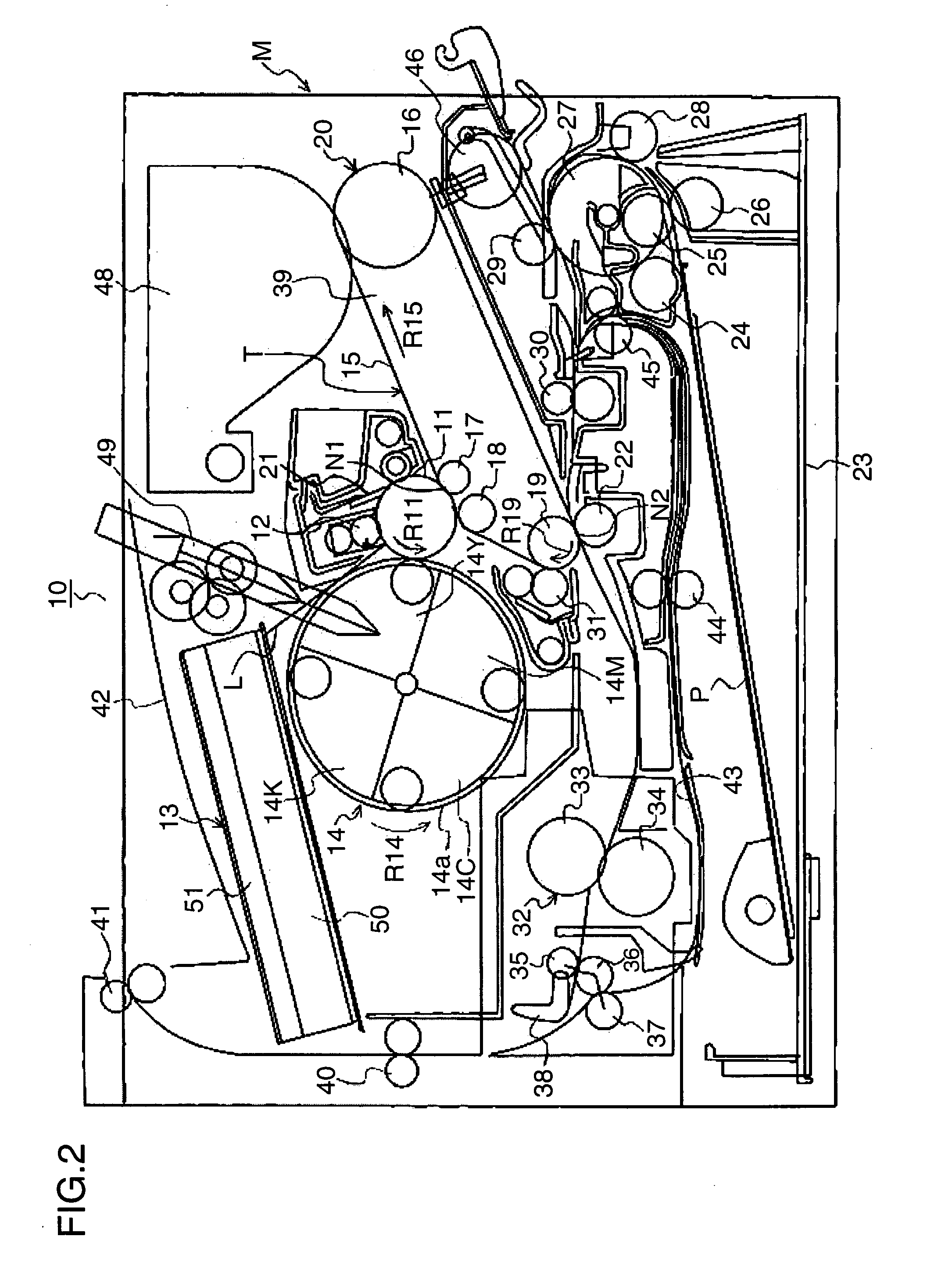
[0024]First, the construction and operation of an image forming apparatus 10 provided with an exposure device 13 according to the present invention are schematically described and, then, the exposure device 13 is described in detail. The image forming apparatus 10 may be a copier, a printer, a facsimile machine or a complex machine of these.

[0025]FIGS. 1 and 2 show the image forming apparatus 10 according to this embodiment. FIG. 1 is a perspective view showing the external appearance of the entire image forming apparatus 10 when viewed obliquel...


PUM


Abstract

An exposure device for exposing the charged surface of a photoconductive drum is provided with a light source for emitting light based on image information; a rotary multifaceted mirror for reflecting the light emitted from the light source to scan the surface of the photoconductive drum; a driving mechanism for drivingly rotating the rotary multifaceted mirror; an inner casing for covering at least the driving mechanism and the rotary multifaceted mirror; and an outer casing for covering the inner casing from the outside. An air vent for communicating the inside and outside of the inner casing is formed in a part of the inner casing facing the rotary multifaceted mirror.

Description

BACKGROUND OF THE INVENTION[0001]1. Field of the Invention[0002]The present invention relates to an exposure device for exposing a photoconductive member in an image forming apparatus such as a copier or a printer, and an image forming apparatus provided with such an exposure device.[0003]2. Description of the Related Art[0004]A light scanning unit (LSU: laser scanner unit) is known as an exposure device of an electrophotographic image forming apparatus such as a copier and a printer. In this LSU, a light emitted from a laser based on image information is caused to be incident on a polygon mirror (rotary multifaceted mirror) rotated at high speed by a polygon motor via a lens, and the resulting reflected light is caused to irradiate the surface of a uniformly charged photoconductive drum via another lens, thereby scanning and exposing the surface of the photoconductive drum. In this way, an electrostatic latent image corresponding to the image information is formed on the surface of...

Claims


Application Information

Patent Timeline
IPC IPC(8): B41J2/435
CPCG02B26/121B41J2/471
Inventor KAWASAKI, KOTARO
Owner KYOCERA DOCUMENT SOLUTIONS INC
Why Eureka
Try Eureka