
Light-mixing type light-emitting apparatus

a light-emitting apparatus and light-mixing technology, which is applied in the direction of light-emitting devices, semiconductor devices for light sources, solid-state devices, etc., can solve the problems of complex design of customized optical lenses or the fabrication process including encapsulation of light-mixing materials with resins, and increase the cost. , to achieve the effect of shortening the mixing distance and improving the light-mixing efficiency of the light-emitting apparatus

Active Publication Date: 2007-11-15
EPISTAR CORP
View PDF16 Cites 30 Cited by
  • Summary
  • Abstract
  • Description
  • Claims
  • Application Information

AI Technical Summary

Benefits of technology

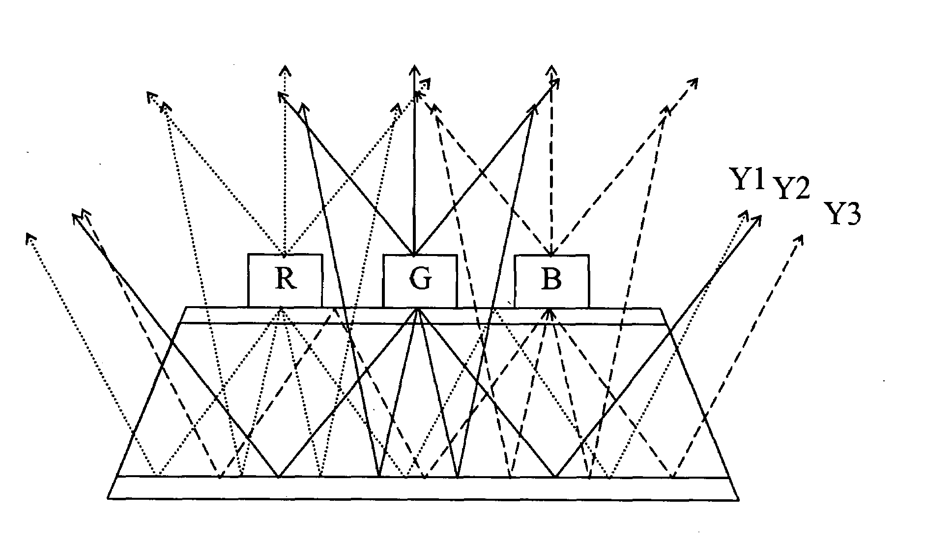
[0006]It is therefore an aspect of the present invention to provide a light-mixing type light-emitting apparatus. The light-emitting apparatus comprises a transparent carrier and a plurality of LEDs. Each of the plurality of LEDs, having a transparent substrate, is formed on the transparent carrier and emits light of a distinct color when driven. The transparent carrier provides a light-mixing zone underlying the plurality of LEDs for the light beams emitted from the plurality of LEDs to mix uniformly so as to improve the light-mixing efficiency of the light-emitting apparatus and shorten the mixing distance.

Problems solved by technology

However, the design of a customized optical lens or the fabrication process including encapsulating the light-mixing materials with a resin is complicated.
Besides, the cost is increased as well.

Method used


Image

  • Light-mixing type light-emitting apparatus
  • Light-mixing type light-emitting apparatus
  • Light-mixing type light-emitting apparatus

Examples


Embodiment Construction

[0021]FIG. 3a shows one embodiment of a light-mixing type light-emitting apparatus in accordance with the present invention. A light-mixing type light-emitting apparatus 30 comprises a transparent carrier 32, a transparent adhesive layer 34 formed on the upper surface of the transparent carrier 32, and a red LED 31a, a green LED 31b, and a blue LED 31c attached to the transparent carrier 32 through the transparent adhesive layer 34. The transparent adhesive layer 34 comprises at least one material selected from the group consisting of Polyimide (PI), Benzocyclobutene (BCB), Perfluorocyclobutane (BFCB), Epoxy resin, and Silicone. The transparent carrier 32 provides a light-mixing zone underlying the LEDs 31a˜31c for the light beams emitted from the LEDs 31a˜31c to mix uniformly into white light within the transparent carrier 32. The light-emitting apparatus 30 further comprises a reflecting layer 33 formed on the lower surface of the transparent carrier 32 for reflecting light beams ...


PUM


Abstract

A light-mixing type light-emitting apparatus comprises a plurality of light-emitting diodes (LEDs) formed on a transparent carrier, wherein each of the LEDs with a transparent substrate emits light of a distinct color when driven, and the light beams generated from the LEDs are mixed to form a specific color. The transparent carrier setting forth in the present invention provides a mixing zone underlying the plurality of LEDs for the light beams to mix uniformly so as to improve the light-mixing efficiency of the light-emitting apparatus and shorten the mixing distance.

Description

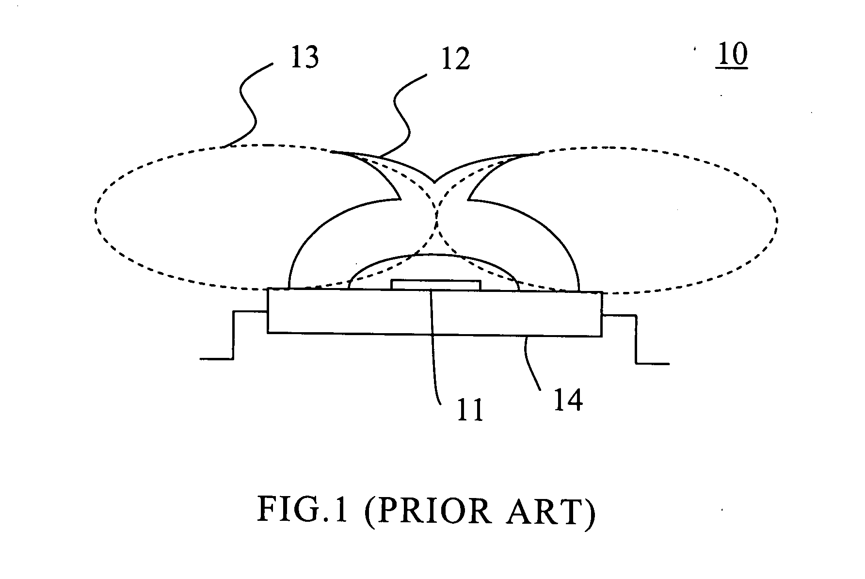
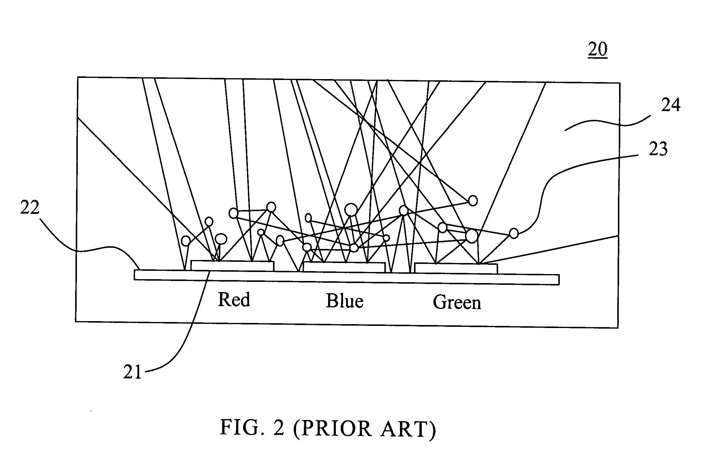
REFERENCE TO RELATED APPLICATION[0001]The present application claims the right of priority based on Taiwan Application Serial Number 095117359, filed on May 15, 2006, the disclosure of which is incorporated herein by reference in its entirety.TECHNICAL FIELD[0002]This invention relates to a light-emitting apparatus and more particularly to a light-mixing type light-emitting apparatus.BACKGROUND[0003]As the luminous efficiency of the light-emitting diode (LED) has been increasing, the extent of the LED applications has become broader and broader, ranging from the traditional indication, lighting sources to various sorts of backlight sources, such as portable flashlights, backlights of mobile phones or liquid crystal displays (LCDs).[0004]Many researches have been widely involved in the development of white light LEDs as LCD backlight sources in order to replace cold cathode fluorescent lamps (CCFL) that have been traditionally used as light sources. One of the related methods is to u...

Claims


Application Information

Patent Timeline
Patent Type & Authority Applications(United States)
IPC IPC(8): F21V9/00
CPCF21K9/00H01L25/0753H01L2224/48091H01L2224/48137H01L2224/49107H01L2224/73265H01L2924/00014H01L2924/00F21K9/62
Inventor HSIEH, MIN-HSUNHSU, CHAI-LIANGHUANG, CHIEN-FULU, CHIH-CHIANGWU, CHUN-YI
Owner EPISTAR CORP
Learn More