Illumination device of flexible lighting angle

a technology of flexible lighting and illumination device, which is applied in the direction of fixed installation, lighting and heating apparatus, lighting support device, etc., to achieve the effect of high efficiency

Inactive Publication Date: 2007-11-15
IND TECH RES INST
View PDF20 Cites 85 Cited by
  • Summary
  • Abstract
  • Description
  • Claims
  • Application Information

AI Technical Summary

Benefits of technology

[0020]In view of the disadvantages of prior art, the primary object of the present invention is to provide an illumination device of flexible lighting angle, being an illumination device using light-emitting diodes (LEDs) as its light source and structured with a light-guide cover with light-control microstructure matching to the LEDs, which is capable of adjusting the light-emitting angle of its LED light source for directing every light emitted from its LED light source to impinge directly upon certain microsurfaces of the light-control microstructure with high efficiency so that not only the angle of the light being discharged out of the illumination device can be control effectively with respect to user's preference, but also the light pattern preferred by a user is achieved and the uniformity of area to be lighted by the illumination device is enhanced.
[0021]It is another object of the invention to provide an illumination device of flexible lighting angle, being an illumination device using light-emitting diodes (LEDs) as its light source, capable of replacing any one LED used thereby easily while it is broken or another LED of different color is preferred by a user as each LED is individually formed on a detachable base.
[0041]By inserting the at least one post into the at least one retaining portion correspondingly for enabling the movable part to be pivotally connected to the seat, the at least one post is able to rotate freely in the corresponding retaining portion in full circumference with respect to an axis of the retaining portion.
[0045]Preferably, the movable part is pivotally connected to the seat whereas the pivotal connection is achieved by inserting the moveable part, shaped as a ball, into a ball-like retaining portion of the seat while enabling the ball to rotate freely in the ball-like retaining portion so as to enable the at least one direction light source received in the moveable part to rotate at any angle at will.

Problems solved by technology

As commonly known that tungsten-filament lamps and energy-saving light bulbs are point sources and fluorescent lamps are line source, all of the abovementioned lamps can only emanate light by an radiating manner such that their light angles are not adjustable.
However, although LEDs are preferred as they are small in size, there are still many to be improved while applying the same in luminaires:(1) As LED is a directional light source, with the maximum emitted power in the direction perpendicular to the emitting surface, that is not suitable to be used in conventional luminaires, a matching reflective cover or a bottom-lighting structure is required.(2) As the brightness produced by a single LED is generally insufficient for most luminaires that it is usual for a luminaire to adopt a plurality of LEDs with fixed lighting angle as its light source, such Multi-LED luminaire with bottom-lighting structure will suffer problems, such as glare, limited illuminant area and unable to produce luminance with sufficient evenness, that cause discomfort to users.(3) As the light emitting from an LED is fixed to a specific direction, the light angle of any reflective or refractive luminaire using such LED as its light source is also fixed so that it is unable to produce various patterns of light and light-emitting angles at will for meeting various luminance requirements and thus it is comparatively not flexible enough.(4) In those conventional LED luminaires, LEDs are usually fixedly arranged on a circuit board so that it is required to dismantle and replace the whole circuit board even when there is only one LED fixed thereon is broken and required to be replaced, and it is difficult for a common consumer to maintain / repair such conventional LED luminaire by himself.(5) It is ease to spot one broken LED or a portion of those in those conventional LED luminaires.
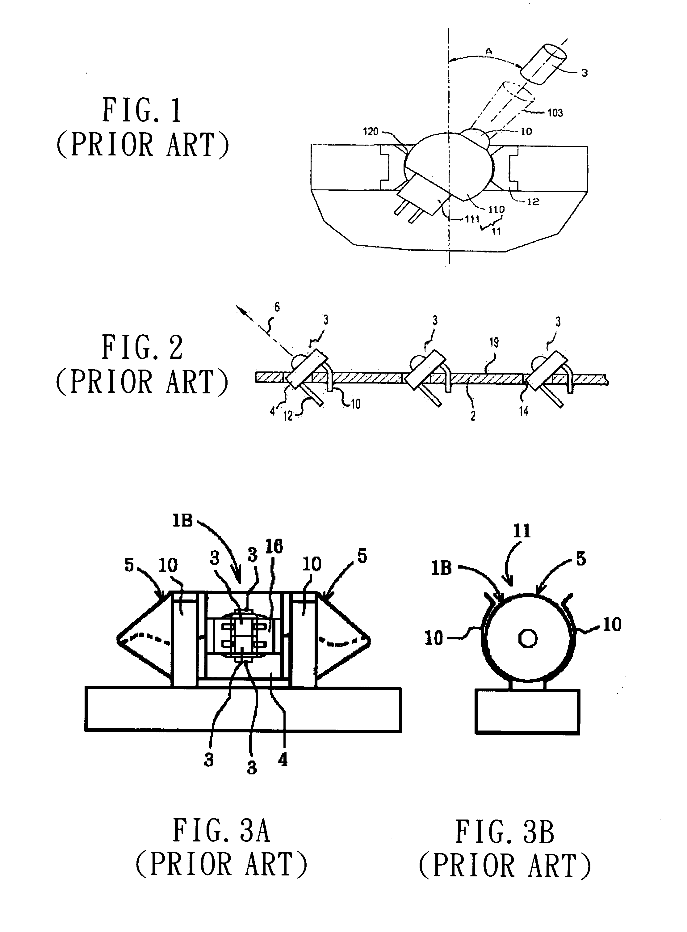
However, as the structure of such rotatable LED arrangement is so complicated and bulky, it is difficult to maintain and assemble.
Moreover, the design of such rotatable LED arrangement limits the LED member 10 to only emit light toward the particular side thereof facing the detector 3 that it can not cover the whole terrain surrounding the arrangement.
In addition, while applying such rotatable LED arrangement to any common luminaire, as the light emitting from such rotatable LED arrangement shoots directly toward the detector 3 and there is no reflective cover configured in such rotatable LED arrangement, it will suffer problems, such as glare, limited illuminant area and unable to produce luminance with sufficient evenness.
In addition, similar to that shown in U.S. Pat. No. 6,315,432, while applying such rotatable LED arrangement to any common luminaire, as the light emitting from such rotatable LED arrangement shoots directly toward the detector 3 and there is no reflective cover configured in such rotatable LED arrangement, it will suffer problems, such as glare, limited illuminant area and unable to produce luminance with sufficient evenness.
As the two LED arrangements, shown respectively in the two aforesaid U.S. patents, both use conventional LEDs with two contact pins as their light sources, the problems troubling those prior-art LED luminaires will also be the problems of the two, such as it is unable to produce various light-emitting angles at will, and it is required to dismantle and replace the whole circuit board even when there is only one LED fixed thereon is broken, and so on.
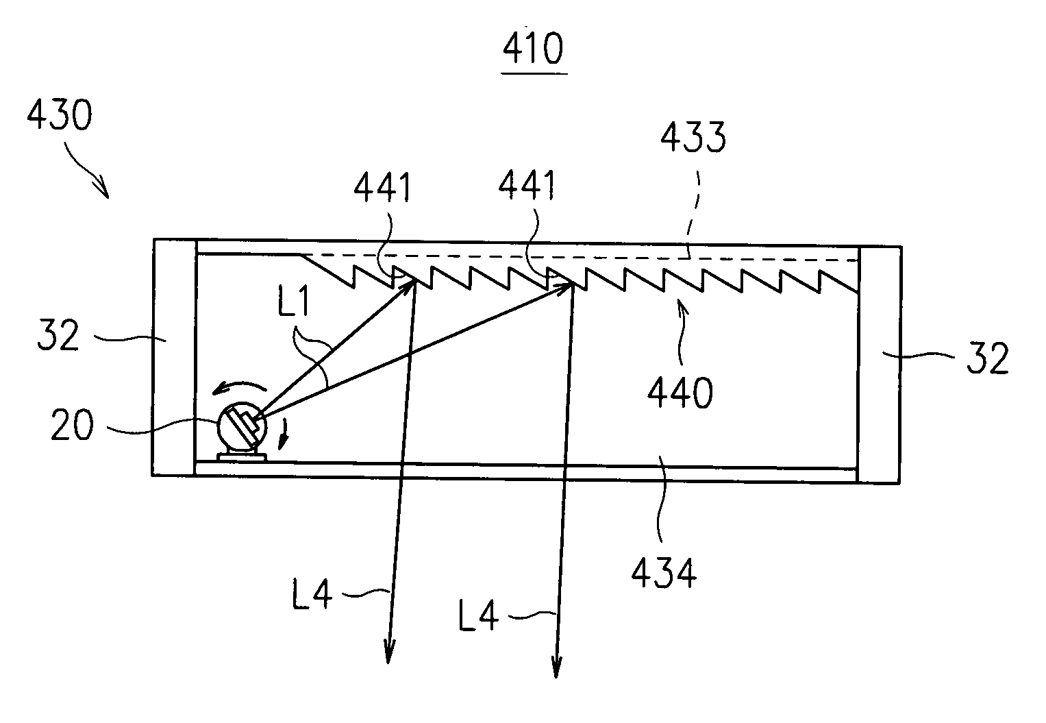
Take a bottom-light LED luminaire for example, although the abovementioned efforts help to improve the light efficiency thereof, but it can not vary the angle of the light being discharged out of the luminaire by adjusting the light-emitting angle of the LEDs and thus not only the light pattern preferred by a user can not be achieved, but also the uniformity of area to be lighted by the illumination device as well as the comfort of users is not preferred.
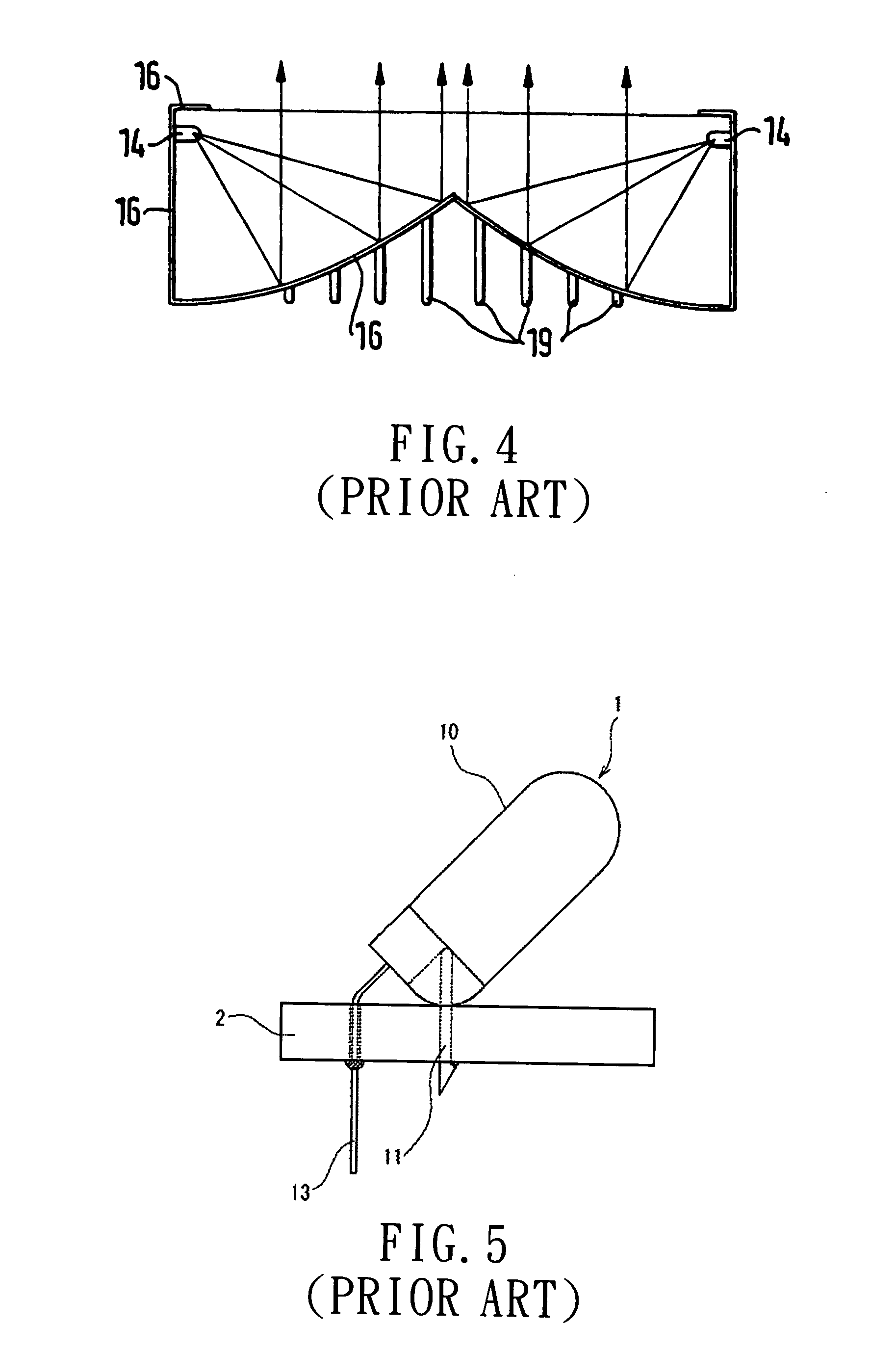
As each LED 14 is being placed flatly at the upper portion of the circumferential edge, the restricted light-emitting angle of such LED 14 will result that only a portion of light emitted therefrom can be reflected by the light-reflecting cover 16 and projected out of the illuminating device in a parallel manner while other portion will be either trapped inside the illuminating device, or being reflected out without shining on a preferred area specified by a user, so that the efficiency of the illuminating device is poor since not all light emitted from the LEDs 14 are utilized.
As there is no reflective means or refractive means being adapted in the LED arrangement, such LED arrangement is prone to suffer from glare.
In addition, it can only adjust its light-emitting angle between 0 degree to 90 degree that an additional set of device is required if some other area out of the adjusting range is required to be illuminated.
Moreover, when the LED 1 is broken and required to be replaced, the replacement operation requires to dismantle the substrate 2 as well which is very troublesome.

Method used


Image

  • Illumination device of flexible lighting angle
  • Illumination device of flexible lighting angle
  • Illumination device of flexible lighting angle

Examples


Embodiment Construction

[0074]For your esteemed members of reviewing committee to further understand and recognize the fulfilled functions and structural characteristics of the invention, several preferable embodiments cooperating with detailed description are presented as the follows.

[0075]Please refer to FIG. 6, which shows a refractive illumination device according to a preferred embodiment of the invention. The refractive illumination device 10 uses a light emitting diode (LED) 20 as its light source that the LED 20, as a directional light source, can be replaced and substituted by another type of directional light source and thus is not limited thereby. The LED 20 is capable of emanating light as being electrically conducted to a control circuit and has ability to adjust a light-emitting angle thereof for varying the angle of the light being discharged therefrom. As seen in FIG. 6, the LED 20 is being received inside a light guide cover 30, which is composed of: a bottom 31; a sidewall 32, vertically ...


PUM


Abstract

An illumination device of flexible lighting angle is disclosed, which comprises: at least a directional light source, capable of emanating a light as it is electrically conducted to a control circuit while enabling the light angle of the light discharged therefrom to be adjustable; and a light guide cover, for receiving the at least one directional light source, having a light-control microstructure formed thereon while enabling the same to be further composed of a plurality of reflective / refractive microsurfaces. By adjusting the light-emitting angle of the directional light source for directing the discharged light to shine on different reflective / refractive microsurfaces of the light-control microstructure where it is reflected / refracted and discharged out of the light guide cover, the angle of the light being discharged out of the light guide cover is varied.

Description

FIELD OF THE INVENTION[0001]The present invention relates to an illumination device of flexible lighting angle, and more particularly, to an illumination device, using light-emitting diodes (LEDs) as its light source and structured with a light-guide cover with light-control microstructure matching to the LEDs, which can vary the angle of the light being discharged out of the illumination device by adjusting the light-emitting angle of the LEDs and thus not only the light pattern preferred by a user can be achieved, but also the uniformity of area to be lighted by the illumination device is enhanced, so that the illumination device can be adapted as luminaires, signal indicators, or other light emitting apparatuses.BACKGROUND OF THE INVENTION[0002]Conventional light sources can be divided into two types of light sources, which are point source and line source. As commonly known that tungsten-filament lamps and energy-saving light bulbs are point sources and fluorescent lamps are lin...

Claims


Application Information

Patent Timeline
Patent Type & Authority Applications(United States)
IPC IPC(8): F21V14/02
CPCF21K9/00F21S8/086F21S48/2212F21Y2101/02F21V7/0008F21V14/02F21W2131/103F21V5/002F21Y2115/10F21S43/26
Inventor LAI, CHIEH-LUNGLIN, JIAN-SHIANLEE, LI-LINGLI, HUNG-CHUN
Owner IND TECH RES INST
Why Eureka
Try Eureka