Merged laser and photogrammetry measurement using precise camera placement

a laser and photogrammetry technology, applied in the field of optical techniques, can solve the problems of large or complicated parts, the length of time required to measure large or complex parts, and the speed of the laser tracker, and achieve the effect of rapid and accurate surface measuremen

Inactive Publication Date: 2007-11-15
THE BOEING CO
View PDF4 Cites 34 Cited by
  • Summary
  • Abstract
  • Description
  • Claims
  • Application Information

AI Technical Summary

Benefits of technology

[0013]The measurement system provides rapid, accurate measurement of surfaces on large or complex parts. A traveling reference system for determining the precise placement of Photogrammetry cameras eliminates the need for placing hardware on the part being measured to assist in establishing the position of the cameras in the measurement volume. The traveling reference system also establishes position information that can be used by a machining center to perform machining operations on the part.

Problems solved by technology

Laser trackers are relatively slow, particularly when measuring large or complex parts, such as a fuselage section of an aircraft.
Each of the measuring techniques described above is less than satisfactory in various respects, particularly in terms of length of time required to measure large or complicated parts.

Method used


Image

  • Merged laser and photogrammetry measurement using precise camera placement
  • Merged laser and photogrammetry measurement using precise camera placement
  • Merged laser and photogrammetry measurement using precise camera placement

Examples


Embodiment Construction

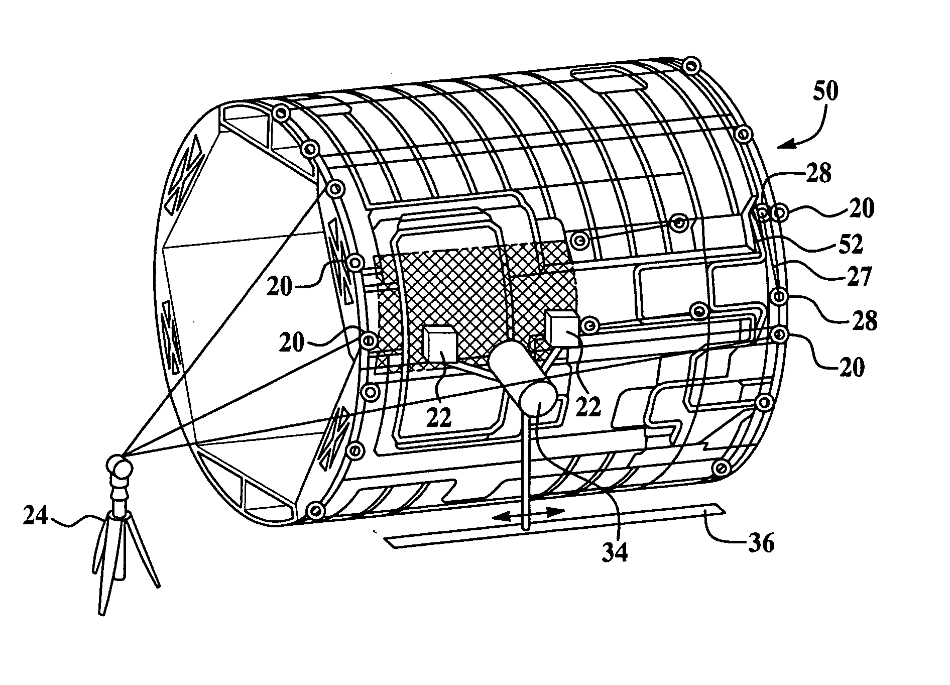
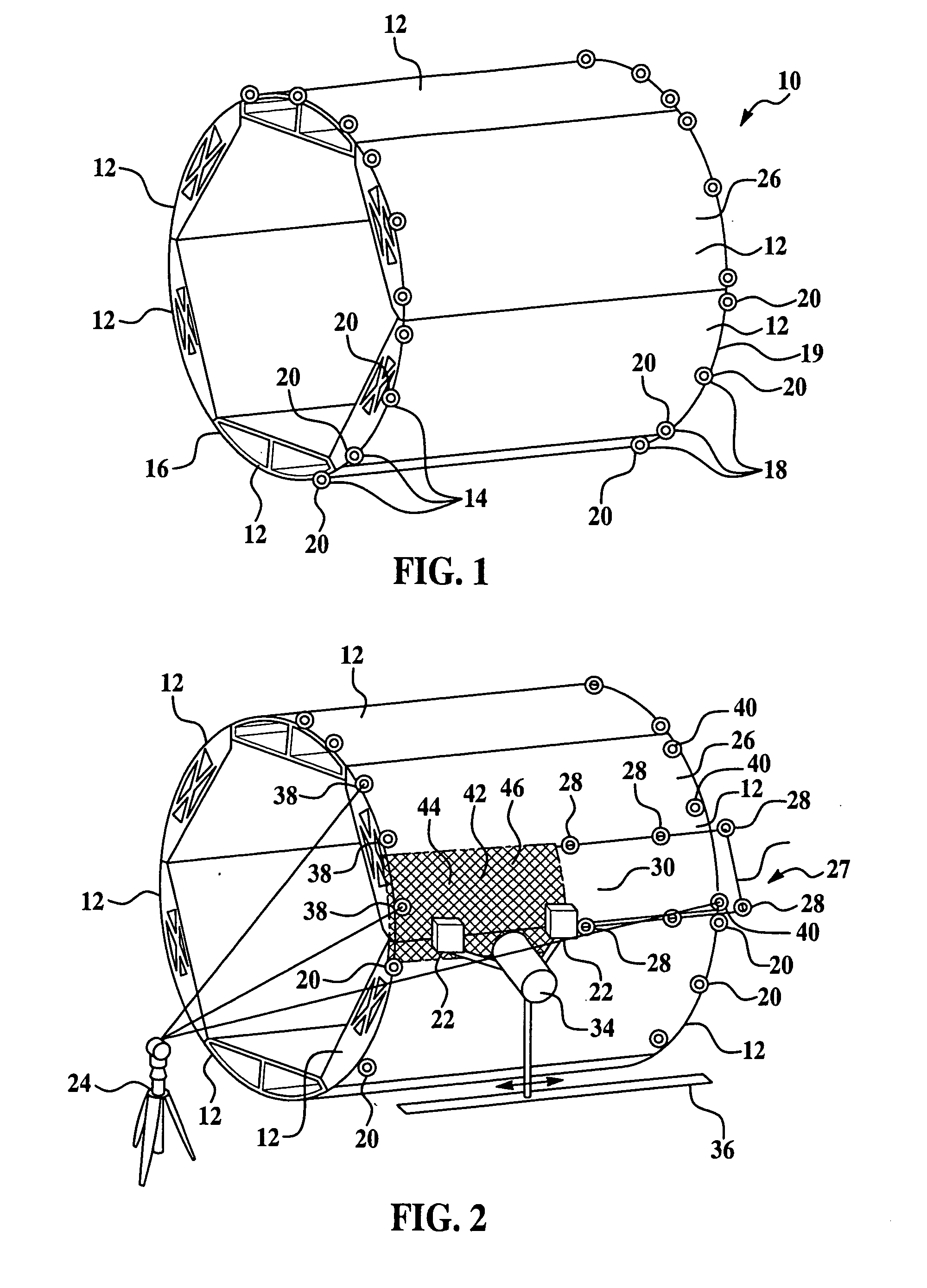
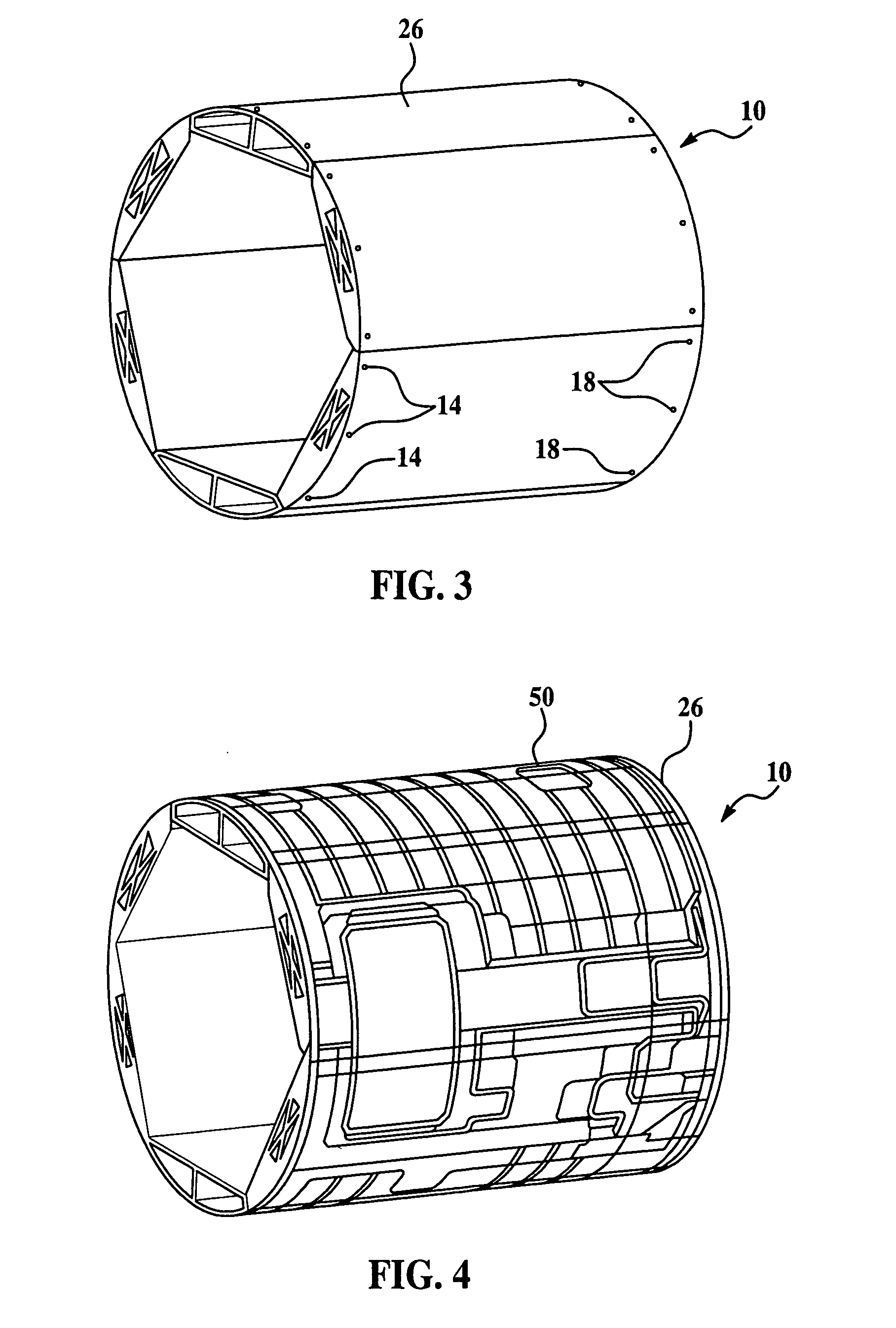
[0032]FIGS. 1 through 6 depict a step by step process for measuring an outer surface of a mandrel assembly and for measuring an outer surface of a barrel of an aircraft. The process may be used, however, to measure one or more differing types of surfaces on any type of part. The surface measuring process may be utilized to measure surfaces in both aircraft and non-aircraft applications.

[0033]FIG. 1 depicts a mandrel assembly 10, which may comprise six steel mandrel sections 12 attached together as with bolts, or other fasteners to form a generally cylindrical shape, or “barrel”. The outer surface 26 of the mandrel assembly 10 includes sixteen lay-up mandrel holes 14 at the forward portion 16 of the mandrel assembly 10 and another sixteen lay-up mandrel holes 18 at the aft portion 19 of the mandrel assembly 10. More or less number of mandrel holes may be used, depending on the particular application. A separate target 20 may be installed on each of the thirty-two mandrel holes 14 and...


PUM


Abstract

The surface of a part is measured using a combination of laser tracking and Photogrammetry processes. Cameras used in the Photogrammetry process are mounted on a carriage for movement to positions along a predetermined path where images of the part surface are recorded and then converted to surface measurements. Laser tracking is used to both measure the part surface and track the position of the cameras. The measurements made by Photogrammetry and laser tracking processes are combined with the camera position to produce highly accurate part surface measurements.

Description

CROSS REFERENCES TO RELATED APPLICATIONS[0001]This application is a continuation-in-part, of U.S. patent application Ser. No. 11 / 432,061, filed May 10, 2006.BACKGROUND OF THE INVENTION[0002]1. Field of the Invention[0003]The present invention generally relates to the use of optical techniques such as Photogrammetry and laser tracking to make precise measurements of part or workpiece features, and deals more particularly with a traveling reference system that provides precise Photogrammetry camera placement information.[0004]2. Description of the Related Art[0005]A variety of processes have been employed to measure one or more surfaces or features of a part or workpiece. Touch probes have commonly been used to make contact measurements of part features or workpiece surfaces. Computer controlled coordinate measuring machines use touch probes to contact surfaces on a part and electronically record the measurements. More recently, “touchless” technologies, such as laser tracking, have b...

Claims


Application Information

Patent Timeline
Patent Type & Authority Applications(United States)
IPC IPC(8): G06F19/00
CPCG01B11/002G01C15/002G01C11/02G01C11/00
Inventor MARSH, BOBBY J.NICHOLS, STEVEN H.
Owner THE BOEING CO
Why Eureka
Try Eureka