
Apparatus for judging condition of injection of reducing agent incorporated in exhaust gas purification system

a technology of exhaust gas purification system and apparatus, which is applied in mechanical apparatus, machines/engines, separation processes, etc., can solve the problems of nox discharge, increase of nox exhaust amount, and excessive ammonia, and achieve the effect of increasing nox

Inactive Publication Date: 2007-11-22
NISSAN DIESEL MOTOR CO
View PDF4 Cites 37 Cited by
  • Summary
  • Abstract
  • Description
  • Claims
  • Application Information

AI Technical Summary

Benefits of technology

[0007] The present invention addresses such problems, with an object of monitoring whether or not the injection condition of the liquid reducing agent is normal, to thereby reduce the exhaust amount of the NOx and prevent discharge of the liquid reducing agent.
[0015] According to the apparatus for judging a condition of injection of reducing agent according to the present invention, attention is directed to the relation with respective elements between the reducing agent consumption and any one of; the travel distance, the fuel consumption, the air consumption and the running time, to continually monitor the injection condition of the liquid reducing agent. Accordingly, abnormal injection of the liquid reducing agent can be found at an early stage, and an increase in the NOx resulting from imperfect NOx purification due to abnormal injection can be prevented. Moreover, when the urea water solution is used as the liquid reducing agent, discharge of ammonia can be prevented.

Problems solved by technology

In a case where the liquid reducing agent is not being normally injection-supplied, for example, taking as one typical example a system that uses a urea water solution as the liquid reducing agent, this gives rise to problems such that if an injection-supply amount of the urea water solution is less than a specified amount, the NOx exhaust amount increases, while on the other hand, if the injection-supply amount of the urea water solution is greater than the specified amount, excessive ammonia, which is not used for the reduction reaction of the NOx, is discharged.

Method used


Image

  • Apparatus for judging condition of injection of reducing agent incorporated in exhaust gas purification system
  • Apparatus for judging condition of injection of reducing agent incorporated in exhaust gas purification system
  • Apparatus for judging condition of injection of reducing agent incorporated in exhaust gas purification system

Examples


first embodiment

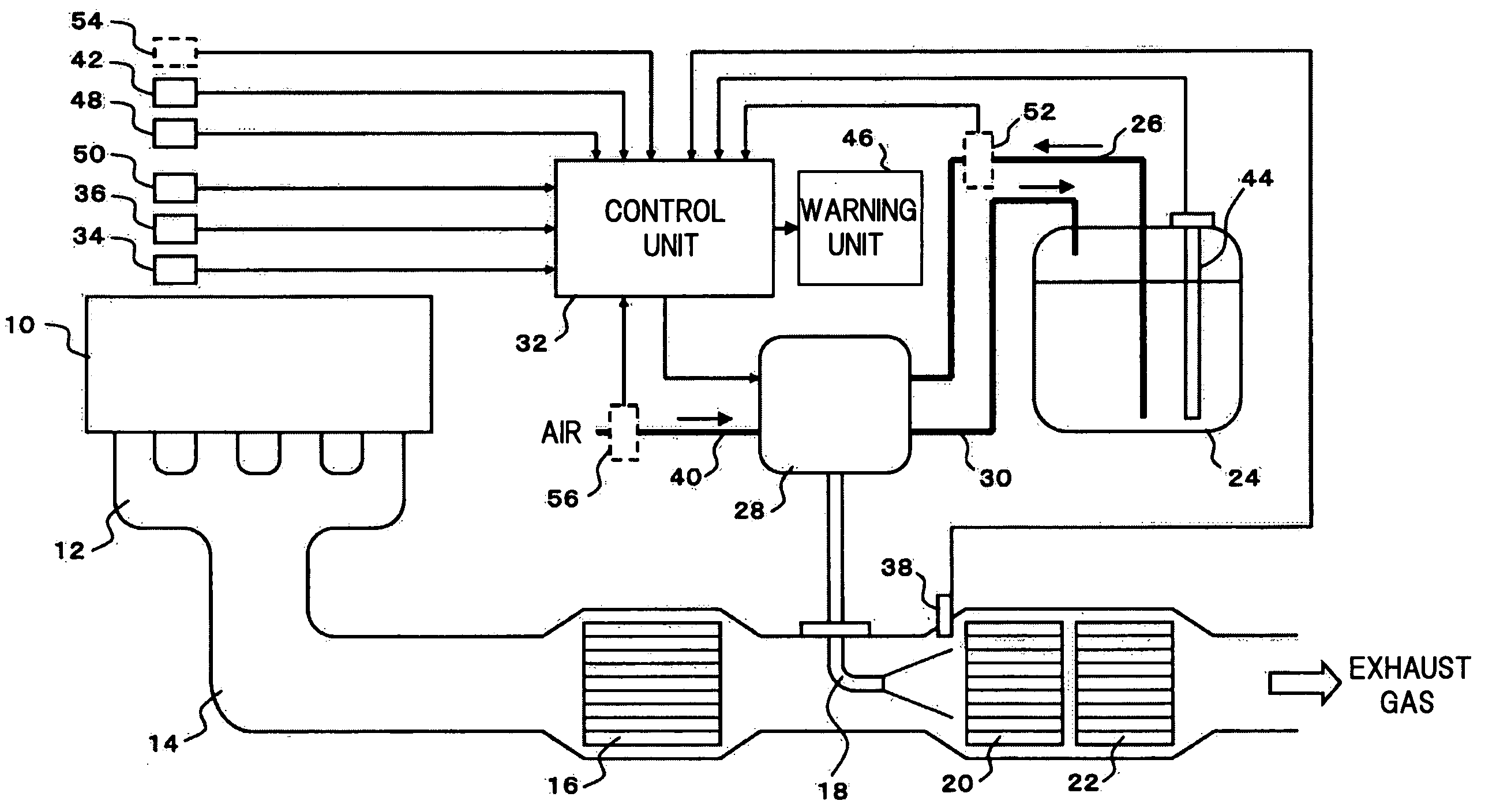
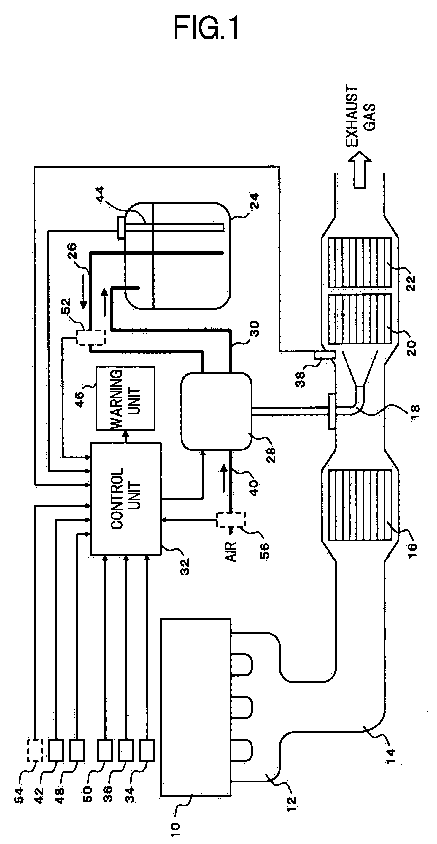
[0026]FIG. 1 shows an overall configuration of an exhaust gas purification system, in which a apparatus for judging a condition of injection of reducing agent, according to the present invention is incorporated, which uses a urea water solution as a liquid reducing agent to purify NOx in an exhaust gas of an engine by a catalytic reduction reaction.

[0027] Referring to FIG. 1, the exhaust gas purification system includes an exhaust pipe 14, which is connected to an exhaust manifold 12 of an engine 10, and there are arranged along an exhaust gas flow direction in the exhaust pipe 14 an oxidation catalyst 16 that oxidizes nitrogen monoxide (NO) to nitrogen dioxide (NO2), an injection nozzle 18 that injection-supplies the urea water solution, a NOx reduction catalyst 20 that reduces and purifies NOx by ammonia obtained by hydrolyzing the urea water solution, and an ammonia oxidation catalyst 22 that oxidizes ammonia having passed through the NOx reduction catalyst 20, respectively. The ...

second embodiment

[0040] Next is a description of the apparatus for judging the condition of injection of reducing agent according to the present invention.

[0041] In the apparatus for judging the condition of injection of reducing agent according to the second embodiment, the configuration is such that the injection condition of liquid reducing agent is judged from a relationship between a fuel consumption and a consumption of the liquid reducing agent, and includes the configuration of a second judgment means that judges that there is abnormal injection of the liquid reducing agent when a consumption of the urea water solution while consuming a predetermined amount of fuel is not within a predetermined range. Accordingly, in this embodiment, a fuel level meter 54 that detects a liquid level inside a fuel tank (not shown) is used for measurement of the fuel consumption, and a measurement signal of the fuel level meter 54 is input to the control unit 32 as shown by the broken line in FIG. 1. The contr...

third embodiment

[0048] Next is a description of the apparatus for judging the condition of injection of reducing agent according to the present invention.

[0049] In the apparatus for judging the condition of injection of reducing agent according to the third embodiment, the configuration is such that the injection condition of liquid reducing agent is judged from a relationship between a consumption of air mixed with the urea water solution and a consumption of the liquid reducing agent, and includes the configuration of a third judgment means that judges that there is abnormal injection of the liquid reducing agent when a consumption of the urea water solution while consuming a predetermined amount of air is not within a predetermined range. Accordingly, in this embodiment, the configuration is such that an air-flow sensor 56 is interposed as shown by the broken line in FIG. 1 in an air pipe 40 connected to the reservoir tank (not shown) to measure the air consumption from a flow rate of air flowin...


PUM

PropertyMeasurementUnit
Temperatureaaaaaaaaaa
Speedaaaaaaaaaa
Distanceaaaaaaaaaa

Abstract

In relation to an exhaust gas purification system that mixes a liquid reducing agent with air and injection-supplies this mixture into an exhaust gas flowing on an upstream side of a reduction catalyst (20) to thereby effect reduction purification of NOx in exhaust gas, a technical attention is directed to the relation of respective elements of; the travel distance, the fuel consumption, the air consumption, or the running time and the like, and the liquid reducing agent consumption, to constitute a configuration such that a continual monitor as to whether the injection condition of liquid reducing agent is normal or abnormal is executed by judging whether or not the amount of liquid reducing agent consumed for a predetermined travel distance, a predetermined fuel consumption, a predetermined air consumption, or a predetermined running time, is within a predetermined range.

Description

[0001] This application is a continuation of PCT / JP2005 / 018261, filed on Oct. 3, 2005.BACKGROUND OF THE INVENTION [0002] 1. Field of the Invention [0003] The present invention relates to an exhaust gas purification system for an engine that injection-supplies a liquid reducing agent into an exhaust gas flowing on an upstream side of a reduction catalyst in the exhaust system of the engine to reduce NOx in the exhaust gas from the engine thereby purifying the exhaust gas before being exhausted into the atmosphere. More particularly, the invention relates to an apparatus for judging a condition of injection of reducing agent (it will be hereinunder referred to as “injection-condition judging apparatus” for the sake of brevity throughout the disclosure.) used in an exhaust gas purification system that monitors whether or not a liquid reducing agent is being normally injection-supplied. [0004] 2. Description of the Related Art [0005] As an exhaust gas purification system which removes t...

Claims


Application Information

Patent Timeline
IPC IPC(8): F01N3/10
CPCB01D53/9431B01D2251/20F01N11/00F01N2550/05F01N2610/02F01N2610/08Y02C20/10F01N2900/08F01N2900/102F01N2900/1814F01N2900/1824Y02T10/47F01N2900/1812F01N2900/0418Y02T10/40
Inventor HIRATA, KIMINOBUMASAKI, NOBUHIKOYANO, MASAKAZU
Owner NISSAN DIESEL MOTOR CO
Learn More