Sewing Machine

a sewing machine and needle technology, applied in the field of sewing machines, can solve the problems of inability to increase the cost of the machine, and inability to control the illuminating device, so as to reduce the manufacturing cost of the illuminating device, reduce the size, and reduce the need for manufacturing cost synergistically

Inactive Publication Date: 2007-11-22
TOKAI IND SEWING MACH CO LTD
View PDF8 Cites 2 Cited by
  • Summary
  • Abstract
  • Description
  • Claims
  • Application Information

AI Technical Summary

Benefits of technology

[0009] By the provision of the illuminating device constructed in the aforementioned manner, the emitted light from the plurality of the unitary light sources disposed at intervals can be gathered, via the lens, to be converted into a linear light beam so that the areas around the points of the individual sewing needles can be illuminated evenly over a wide range with a small number of the unitary light sources, which can thereby minimize the manufacturing cost of the illuminating device. Further, in cases where the present invention is applied to a multi-head sewing machine, the necessary manufacturing cost can be reduced synergistically. Furthermore, where chip LEDs (Light Emitting Diodes) are used as the unitary light sources, the unitary light sources not only can be reduced in size and increased in operating life but also can effectively prevent undesired heat production.
[0010] By controlling each of the machine heads in response to an operating state of the...

Problems solved by technology

However, because illumination (light emission) by the LED lamp as a unitary light source is limited to a small spot-shaped range, a multiplicity of LED lamps have to be disposed in a linear array with almost no gap in order to illuminate areas around the points of the individual needles of a multi-needle sewing machine, which would inevitably require an increased cost.
With a multi-head, multi-needle type sewing machine including a plurality of multi-needle type machine h...

Method used


Image

  • Sewing Machine
  • Sewing Machine
  • Sewing Machine

Examples


Embodiment Construction

[0017] Embodiments of the present invention will hereinafter be described with reference to the accompanying drawings.

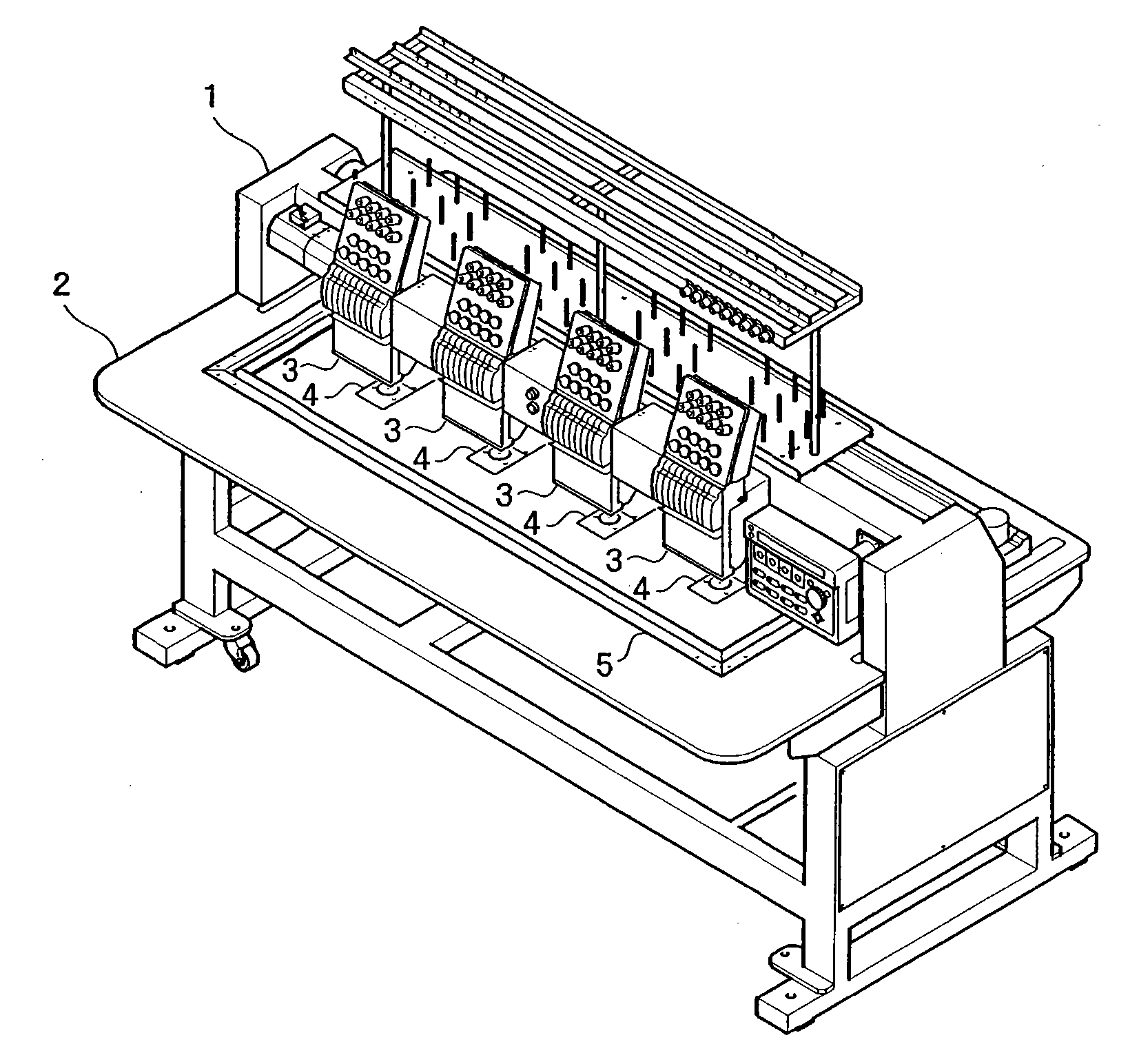
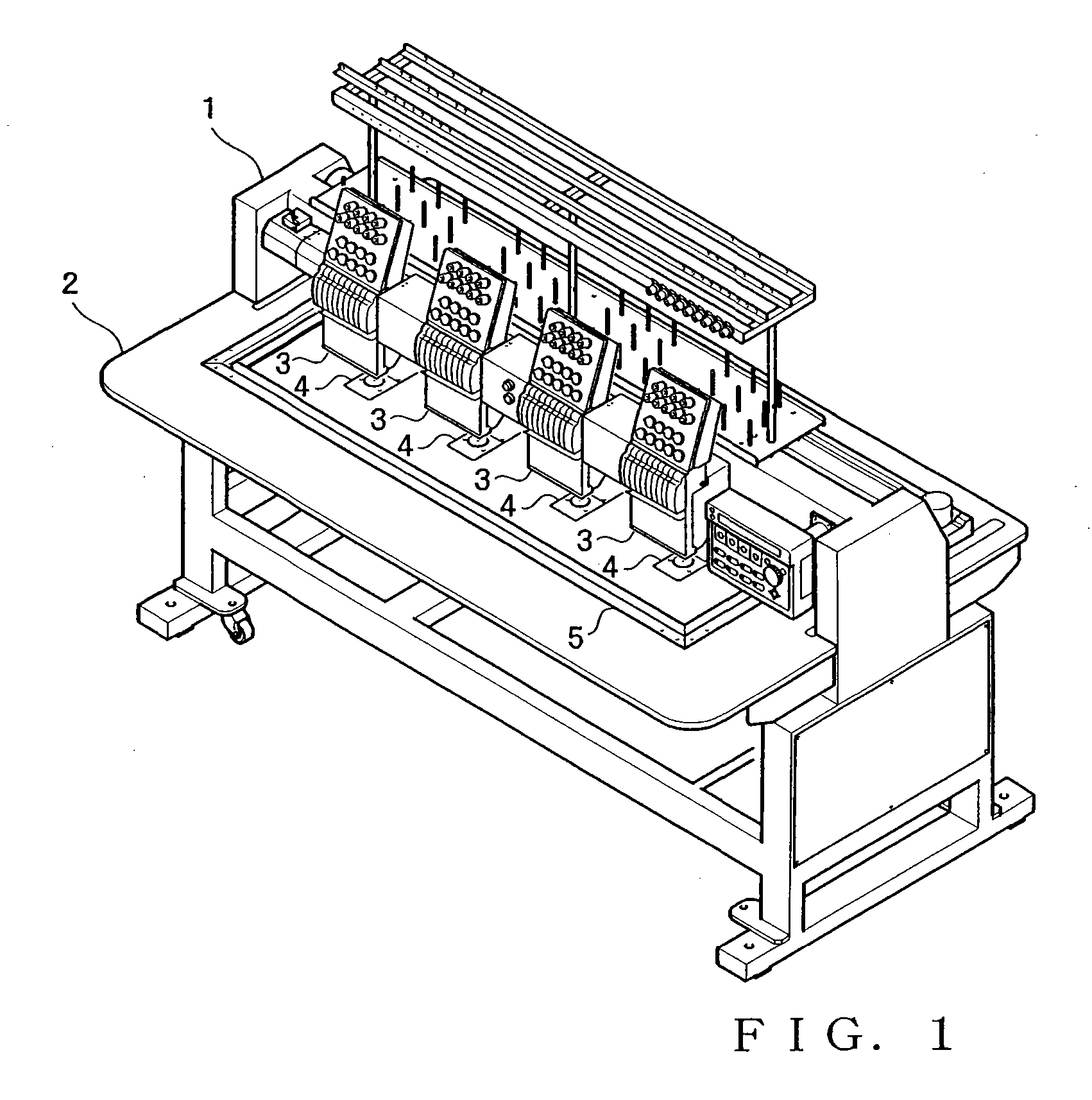
[0018]FIG. 1 is a view showing an outer appearance of a multi-head, multi-needle embroidery sewing machine in accordance with an embodiment of the present invention, where reference numeral 1 indicates a machine frame, and 2 a table. A plurality of (four in the illustrated example) machine heads 3 are disposed at equal intervals along a left-right horizontal direction of the sewing machine, and a needle plate 4 is disposed immediately beneath each of the machine heads 3 and at generally the same height position as the table 2. On the upper surface of the table 2, there is placed an embroidery frame 5 that is driven in front-rear and left-right horizontal directions via an X-axis drive mechanism and Y-axis drive mechanism (not shown).

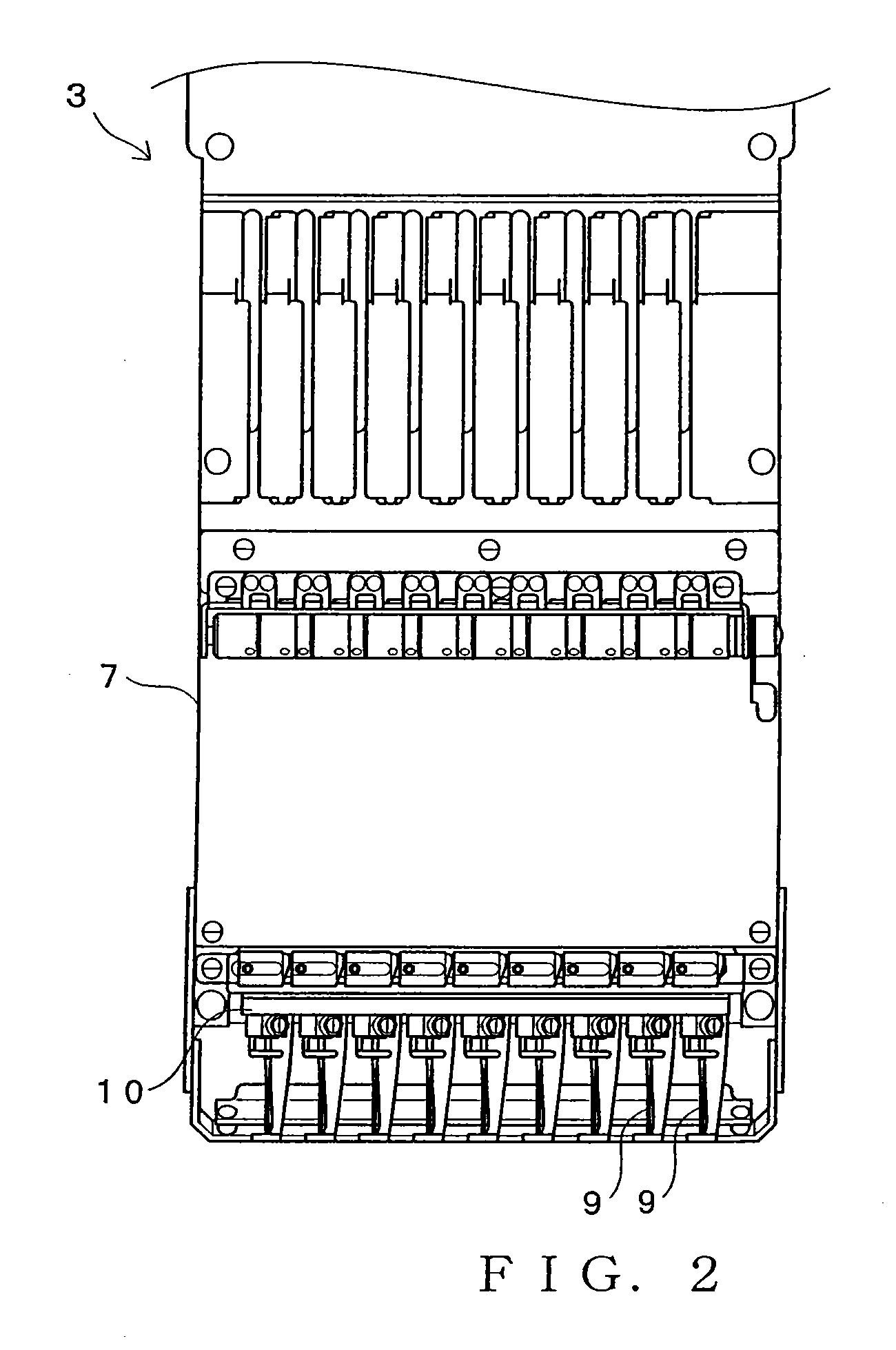
[0019]FIG. 2 is a front view of the machine head 3, and FIG. 3 is a side view (partly in section) of the machine head 3. As clear from...


PUM


Abstract

Illuminating device includes a plurality of LEDs positioned at intervals so as to form a linear LED array generally corresponding to an array line along which needle bars are provided, and a lens for gathering emitted light from the LEDs to thereby generate a linear light beam corresponding to the array line. The illuminating device provided in each machine head is controlled, independently of the illuminating devices of the other machine heads, in response to an operating state of the machine head. Thus, it is possible to not only generate, at low cost, a linear light beam suited to illumination of areas around the points of a plurality of needles arranged in a linear array, but also appropriately control the needle point illumination for the plurality of machine heads.

Description

TECHNICAL FIELD [0001] The present invention relates to sewing machines provided with an illuminating device for illuminating areas around needle points immediately beneath a machine head. BACKGROUND ART [0002] Heretofore, there have been known sewing machines provided with an illuminating device for illuminating areas around the points of needles (i.e., needle points) and surface of a sewing fabric so that needle threading operation and inspection of a pattern sewn on a sewing fabric can be performed with ease. Japanese Patent Application Laid-open Publication No. HEI-11-253685 discloses a sewing machine which includes a plurality of needle bars provided on a machine head, and an illuminating device for illuminating an area around the point of a needle fixed to the lower end of each needle bar and surface of a sewing fabric. The illuminating device, which is capable of emitting a linear light beam generally along an array line along which the needle bars are disposed, comprises, fo...

Claims


Application Information

Patent Timeline
IPC IPC(8): D05B55/00D05B79/00
CPCD05B79/00D05C13/00
Inventor TAJIMA, IKUOHASEGAWA, HIDEOFUJIMOTO, SHINYA
Owner TOKAI IND SEWING MACH CO LTD
Why Eureka
Try Eureka