Supercharge Your Innovation With Domain-Expert AI Agents!

Simulated solar light irradiation apparatus

Inactive Publication Date: 2007-11-22
NAT INST OF ADVANCED IND SCI & TECH
View PDF3 Cites 20 Cited by
  • Summary
  • Abstract
  • Description
  • Claims
  • Application Information

AI Technical Summary

Benefits of technology

[0011]In view of the above-mentioned circumstances, an object of the present invention is to provide a simulated solar light irradiation apparatus with improved uniformity of light on a test piece surface by arranging a plurality of filters, between a light emission portion and a test piece, on a plane substantially vertical to an optical axis.
[0016]In conventional simulated solar light irradiation apparatus, to achieve light irradiance distribution with favorable uniformity on a test piece surface, the positions of the light source, mirror, lens or the like are required to be precisely adjusted. Moreover, uniformity of light irradiance is restricted by the precisions of these optical components and the apparatus size. Thus, the uniformity is often restricted to about ±2% to ±5%. However, according to the simulated solar light irradiation apparatus of the present invention, light uniformity is adjusted by the filters disposed between the light emission portion and the test piece surface. Therefore, exactness is not required for the manufacturing precision and position adjustment of the optical components, thereby achieving a uniformity of about ±1% to ±2%. Furthermore, in the prior art, it has been required to secure a long distance between the light emission portion and the test piece surface in order to obtain light irradiance distribution with favorable uniformity. However, according to the simulated solar light irradiation apparatus of the present invention, it is possible to improve uniformity without such restrictions.
[0017]Furthermore, in the prior art, uniformity of light irradiance distribution on the test piece surface has sometimes varied depending on the wavelength of light. However, in the present invention, it is possible to easily obtain light irradiance distribution with favorable uniformity by use of filters with different spectral transmittance.

Problems solved by technology

However, these curved-surface optical components have had a problem that they are difficult to manufacture and expensive.
Furthermore, relative positions and angles of the lamp, the elliptic mirror, and the lens have been required to be individually adjusted, which leads to a problem of cumbersome adjustments of the optical system including the lamp and the elliptic mirror or the like.
In this case, however, the distance between the light source and the integrator lens and the distance between the integrator lens and the test piece need to be long.
As a result, there has been a problem that the apparatus is made larger to obtain irradiation with favorable uniformity on the test piece surface.
However, there has been a problem that a light source with high irradiance is required, since of the light from the light source, only light directly irradiated in the direction of the test piece is utilized.

Method used


Image

  • Simulated solar light irradiation apparatus
  • Simulated solar light irradiation apparatus
  • Simulated solar light irradiation apparatus

Examples


first embodiment

[0025]the present invention will be described with reference to FIG. 1 and FIG. 2.

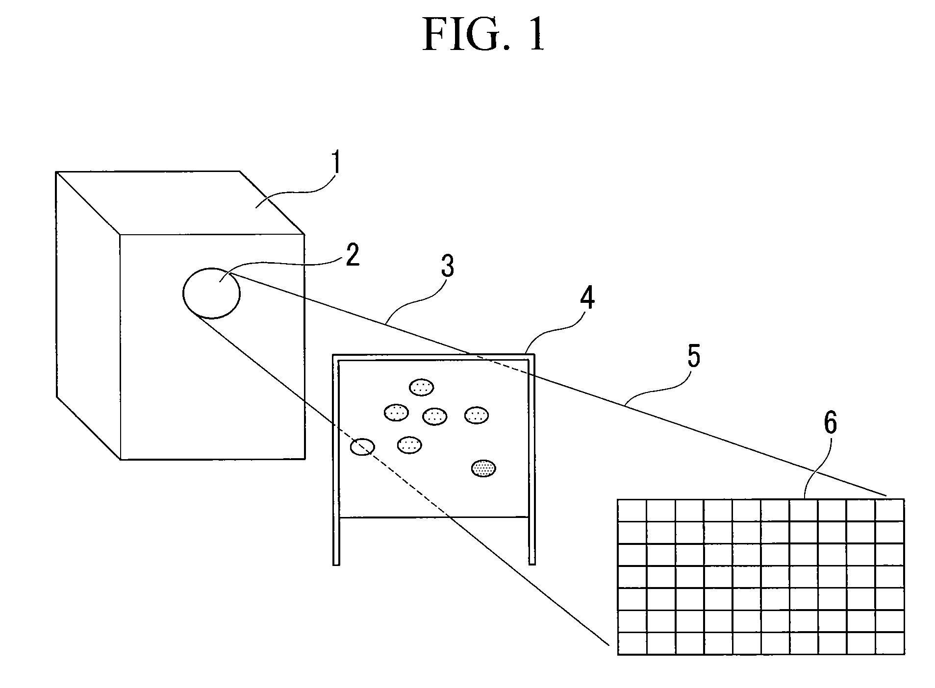
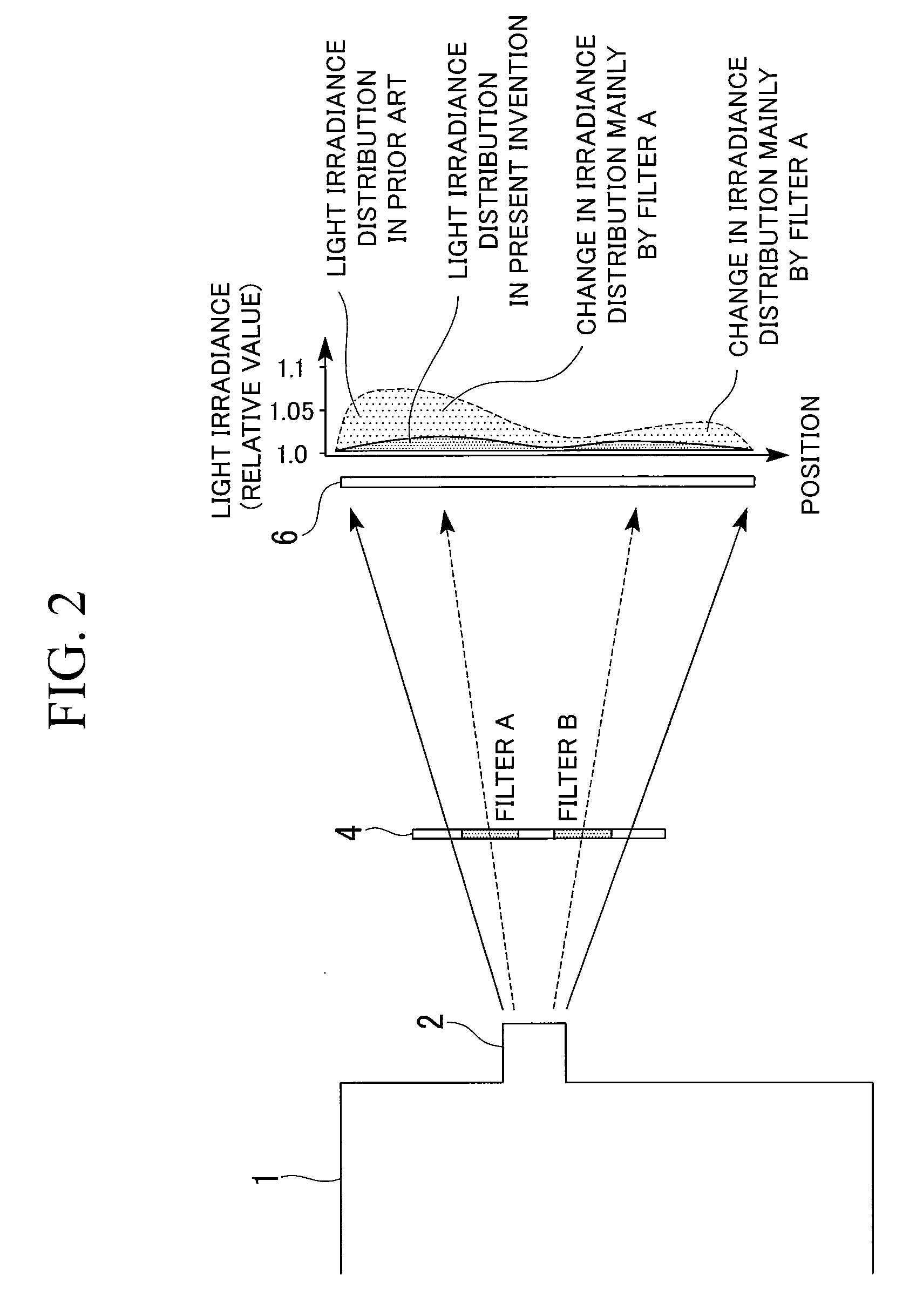
[0026]FIG. 1 is a perspective view showing a configuration of a simulated light irradiation apparatus according to this embodiment of the invention. FIG. 2 is a front cross-sectional view of the simulated light irradiation apparatus shown in FIG. 1.

[0027]This simulated solar light irradiation apparatus is a solar simulator that irradiates simulated solar light onto a solar cell module as a test piece 6. For a light source portion 1, a xenon lamp is used. Light emitted from a light emission portion 2 is irradiated onto the test piece 6. Between the light source portion 1 and the test piece 6, a plurality of filters A and B in a filter portion 4, which is supported by a frame, is provided. The filters A and B adjust the distribution of light emitted from the light emission portion 2 to improve light uniformity on a surface of the test piece 6. When the filter portion 4 is not provided, light irradiance d...

second embodiment

[0030]Next, the present invention will be described with reference to FIG. 3.

[0031]FIG. 3 is a perspective view showing a configuration of a simulated light irradiation apparatus according to this embodiment of the invention.

[0032]Conventionally, non-uniformity of irradiance on the test piece 6 surface sometimes varies depending on the wavelength of light. This is because a region with more intense visible light and a region with more intense infrared light are present on the test piece 6 surface as shown in FIG. 3, in the case where one or more types of lamps, for example, a xenon lamp and a halogen lamp, are used for the light source portion 1, where a light source with a function capable of varying the spectral irradiance of the light source with a multi-layered film filter or the like or where chromatic aberration of the optical system exists. In this case, according to the simulated solar irradiation apparatus of the present invention, one or more types of filters are disposed ...

third embodiment

[0033]Next, the present invention will be described with reference to FIG. 4 and FIG. 5.

[0034]FIG. 4 is a side view showing a configuration of a simulated light irradiation apparatus according to this embodiment of the invention. FIG. 5 is an enlarged front view showing the filter portion 4 shown in FIG. 4.

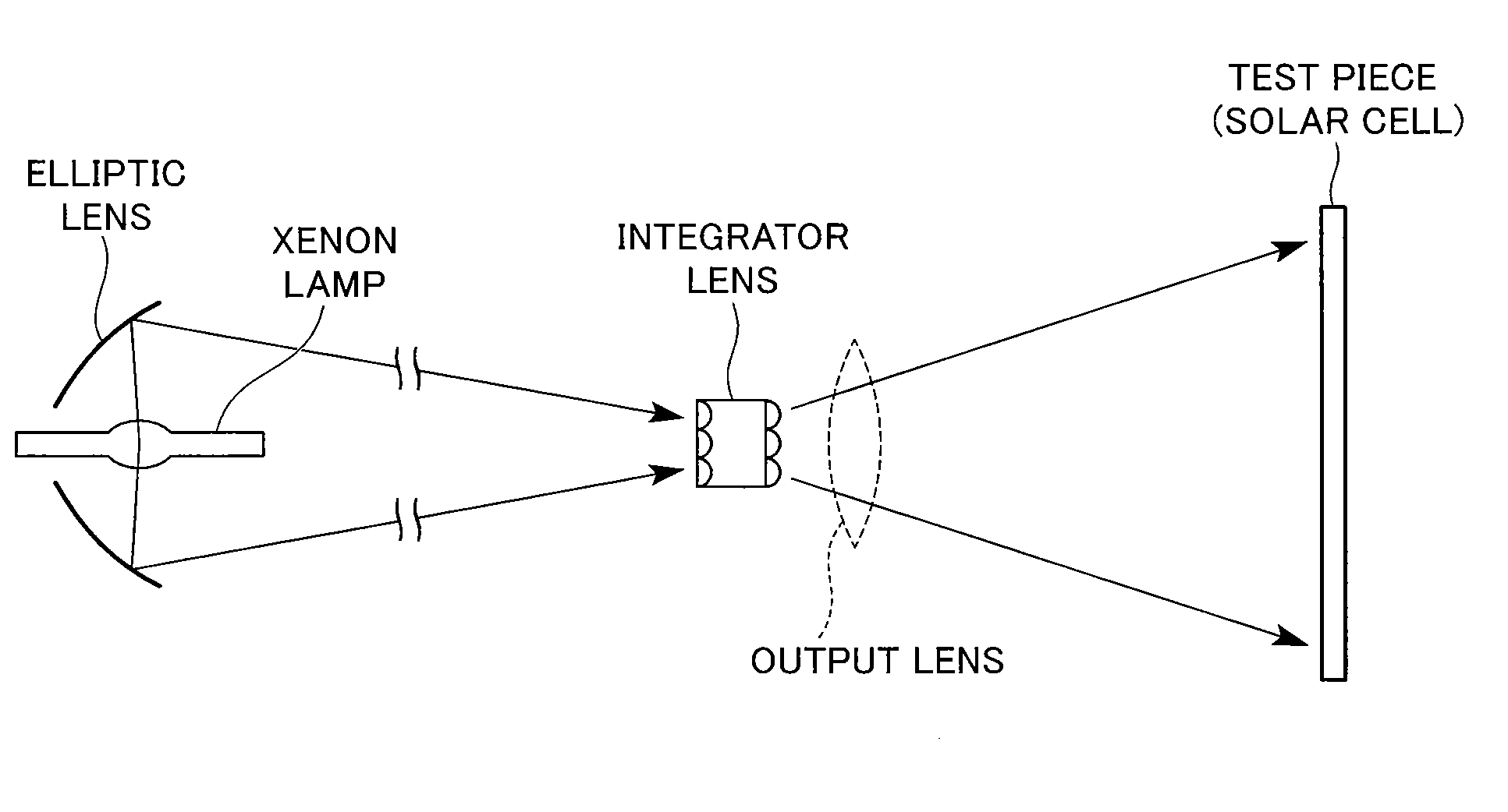
[0035]In FIG. 4, an integrator lens 7 and an output lens 8 correspond to the configuration of the light emission portion 2 shown in FIG. 1 or the like. Substantially parallel light is irradiated from the output lens 8 toward the test piece 6 via the filter portion 4.

[0036]In the filter portion 4, as shown in FIG. 5, grid wires 10 made of metal wires or resin wires with a diameter of 0.1 mm are spaced 5 cm apart in the filter frame 9. The filters are fixed onto the grid wires 10. The positions and wire thickness of the grid wires 10 are selected so as not to adversely affect light uniformity on the test piece 6 surface. As for the types of the filters, mesh filters 11 made of metal...


PUM


Abstract

A simulated solar light irradiation apparatus is provided which irradiates light onto a test piece 6, in which a plurality of filters 4 for improvement in the uniformity of light on a surface of the test piece 6 are arranged, between a light emission portion 2 and the test piece 6, on a plane substantially vertical to an optical axis.

Description

BACKGROUND OF THE INVENTION[0001]1. Field of the Invention[0002]The present invention relates to a simulated solar light irradiation apparatus for use as a light source in estimation of performance of a solar cell or in a light environmental test apparatus or the like. Priority is claimed on Japanese Patent Application No. 2006-137096, filed on May 16, 2006, the content of which is incorporated herein by reference.[0003]2. Description of Related Art[0004]In solar simulators, optical systems having a curved surface such as integrator optical systems (fly eye lens optical systems) have been conventionally used in order to irradiate light with uniformity within several percentages on the entire surface of a test piece. Here, a solar simulator is an apparatus for irradiating light that simulates the intensity and spectrum of sunlight onto a test piece such as a solar cell. The required performance of a solar simulator is described in, for example, JIS (Japanese Industrial Standards) C89...

Claims


Application Information

Patent Timeline
IPC IPC(8): H02N6/00
CPCF21S8/006G01J1/08G01J1/0488
Inventor HISHIKAWA, YOSHIHIRO
Owner NAT INST OF ADVANCED IND SCI & TECH
Features
  • R&D
  • Intellectual Property
  • Life Sciences
  • Materials
  • Tech Scout
  • Unparalleled Data Quality
  • Higher Quality Content
  • 60% Fewer Hallucinations
Learn More