
Lifting pump for manganese nodules

a lifting pump and manganese nodule technology, applied in the direction of liquid fuel engines, mechanical machines/dredgers, machines/engines, etc., can solve the problems of increasing the cost of mining, reducing the time and cost of mining, and hard and brittle when dried, so as to reduce the cost and time of mining

Inactive Publication Date: 2007-11-22
KOREA INST OF GEOSCI & MINERAL RESOURCES
View PDF11 Cites 4 Cited by
  • Summary
  • Abstract
  • Description
  • Claims
  • Application Information

AI Technical Summary

Benefits of technology

[0020]Accordingly, the present invention has been made keeping in mind the above problems occurring in the related art, and a first object of the present invention is to provide a lifting pump for manganese nodules, in which an inflow port can be precisely positioned at the seabed covered with the manganese nodules, so that a lot of manganese nodules can be mined using a small quantity of inflowing seawater, and thus the mining time and cost can be reduced.
[0021]A second object of the present invention is to provide a lifting pump for manganese nodules, in which the manganese nodules pumped pass through a fluid passage surrounding the motor, so that a fluid passage structure becomes simple, to thus eliminate the fear that the sludge or manganese nodules will become stuck, and thus stable operation is possible to not only increase the operational stability of the product but also considerably decrease the likelihood of damage to the pump.
[0022]A third object of the present invention is to provide a lifting pump for manganese nodules, in which a mechanical seal is used as a shaft sealing device, so that the sludge does not penetrate into the shaft sealing device, and thus maintenance expenses are very small.
[0023]A fourth object of the present invention is to provide a lifting pump for manganese nodules, in which a flexible hose is installed at the lower end of the pump, so that the manganese nodules can be easily pumped up under any situation.
[0025]A sixth object of the present invention is to provide a lifting pump for manganese nodules, in which a pump unit is integrally formed with a pumping motor, so that the installation is easy, and a separate shaft joint is not required.
[0026]A seventh object of the present invention is to provide a lifting pump for manganese nodules, in which the center of gravity is located in the middle of the pump, so that the pump is easily installed, and the stable operation is possible without being influenced by ocean current.

Problems solved by technology

Generally, deep-seabed manganese nodules are flat or nodular, dark brown amorphous concretions, which are soft when mined, but are hard and brittle when dried.
To maintain an optimal position of the buffer relative to the collector is almost impossible using only a dynamic positioning system (DPS) of the marine mining ship in spite of the exact consideration of a dynamic behavior of the lifting pipe.
However, the liquid ring pump having this construction has the following problems.
Due to the distance between the lower portion of the pump and the seabed, if the sludge and the manganese nodules are not floated even though the seawater is ejected through the ejection pipe, a lot of unnecessary seawater must be additionally sucked in.
Hence, the quantity of the manganese nodules per unit volume of the seawater is low, which results in increasing the mining cost.
Second, because the inflow port is installed in the middle of the pump body, the strainer frequently blocks the inflow port, thus degrading inflow conditions, so that the motor fails to perform its normal function.
Third, the manganese nodules that have been sucked in have a high possibility of being jammed between the impeller and the shaft of the motor while passing through the motor.
This entails a high possibility of damage to the motor.
Fourth, because the pump is long, there remains difficulty installing the motor.
Fifth, because the motor is in contact with the seawater, the motor has a high possibility of being corroded by the seawater.

Method used


Image

  • Lifting pump for manganese nodules
  • Lifting pump for manganese nodules
  • Lifting pump for manganese nodules

Examples


Embodiment Construction

[0036]Reference will now be made in greater detail to an exemplary embodiment of the invention, an example of which is illustrated in the accompanying drawings. Wherever possible, the same reference numerals will be used throughout the drawings and the description to refer to the same or like parts.

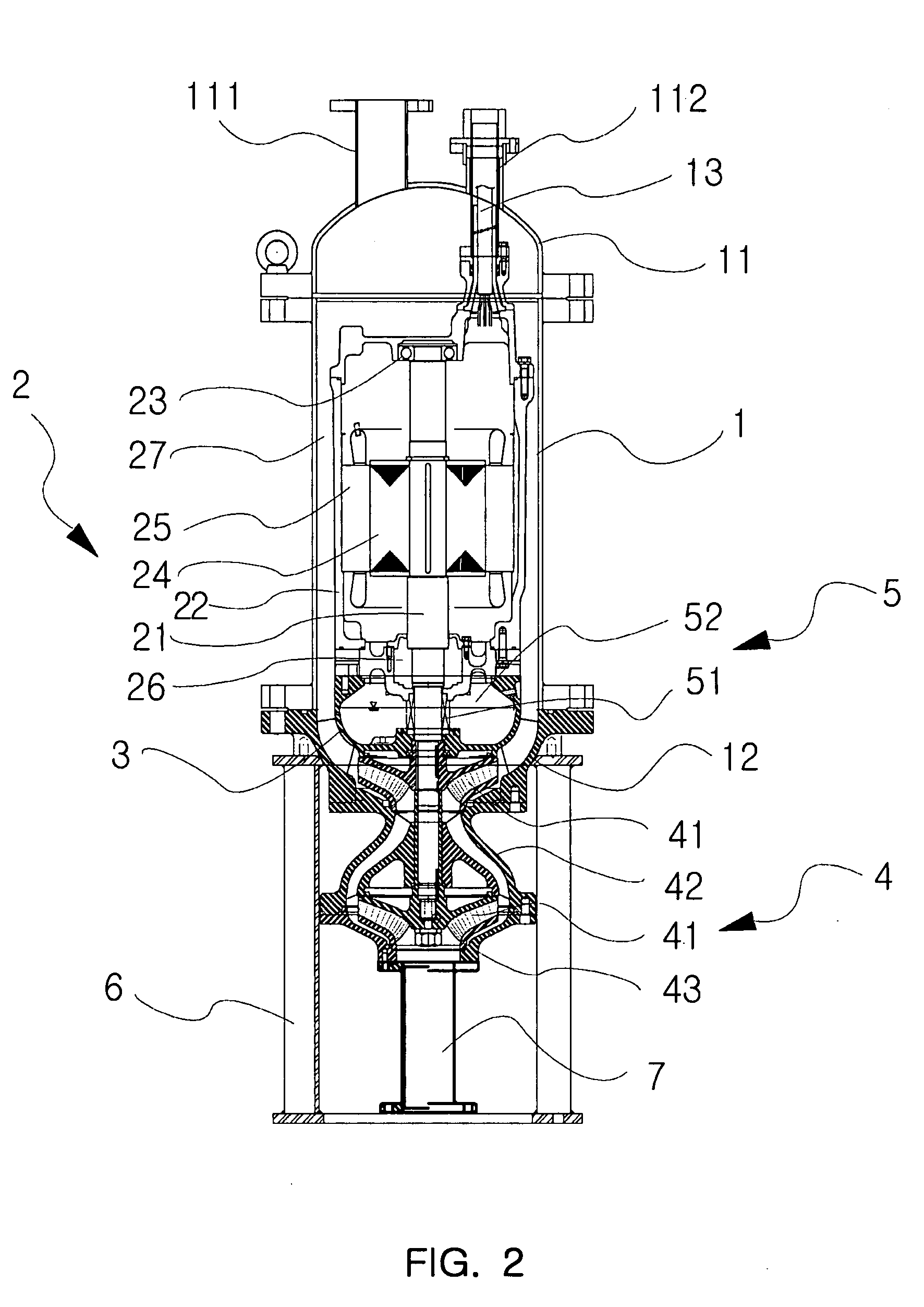
[0037]FIG. 2 is a sectional view illustrating a lifting pump according to an embodiment of the present invention. FIG. 3 is an enlarged sectional view illustrating the important part of a lifting pump according to an embodiment of the present invention. FIG. 4 is a sectional view illustrating a lifting pump according to another embodiment of the present invention.

[0038]As illustrated, a lifting pump of the present invention includes:

[0039]a cylindrical body 1 that is sealed at upper and lower portions thereof by a semi-spherical upper cap 11 having a fluid outflow port 111, which is connected with a marine mining ship through a lifting pipe, and a cable insertion tube 112, and by a semi-s...


PUM


Abstract

A lifting pump for manganese nodules includes: a cylindrical body that is sealed at upper and lower portions thereof by a semi-spherical upper cap having a fluid outflow port and a cable insertion tube, and by a semi-spherical lower cap to which an inflow case of a pump unit is coupled; a pumping motor that has a fluid passage formed between an inner surface of the body and an outer surface thereof, is vertically fixed in the body, and drives the pump unit using electric power supplied through a cable; a cover that provides a seal around a shaft of the pumping motor; the pump unit that is installed between the shaft of the pumping motor and the semi-spherical lower cap, is driven by the rotation of the pumping motor, and lifts seawater together with the manganese nodules; a sealing means that provides a seal between the pumping motor and the pump unit; and a reducer that is coupled to the bottom of the pump unit and guides the seawater including the manganese nodules to the pump unit.

Description

BACKGROUND OF THE INVENTION[0001]1. Field of the Invention[0002]The present invention relates, in general, to a lifting pump for manganese nodules, and more particularly, to a lifting pump for manganese nodules, in which a motor is installed in an upper portion of the lifting pump, a pump unit is installed at a lower end of the motor, and an inflow port for free suction is installed at a lower end of the lifting pump, thereby allowing suction under any adverse situation; in which the manganese nodules pumped by the pump unit pass through a separate fluid passage, thereby pre-emptively preventing a shaft of the pump unit from being restricted; in which a low lifting pump is produced for the sake of user's convenience of installing the lifting pump, thereby securing the stability of position fixture in the installed state; and in which the pumping motor is waterproofed by a combination of an O-ring and a mechanical seal, thereby increasing durability, reducing energy consumption and t...

Claims


Application Information

Patent Timeline
Patent Type & Authority Applications(United States)
IPC IPC(8): E02F3/88
CPCE02F3/88E02F3/90F04D13/10F04D7/04E21C50/00F04D11/00F04D29/106F04D29/056F16J15/16F04D29/002
Inventor YOON, CHI-HOKIM, YOUNG-JUPARK, YONG-CHANKWON, SEOK-KIYANG, TAE-YUAL
Owner KOREA INST OF GEOSCI & MINERAL RESOURCES
Learn More