
Wireless communication terminal and mobile type wireless communication terminal

a wireless communication terminal and wireless technology, applied in the direction of electric variable regulation, process and machine control, instruments, etc., can solve the problems of increasing the cost, reducing the size of the mobile telephone handset, and complicating the hinge structure or packaging process, so as to reduce the quality of the internal wireless communication, reduce the quality of the external wireless communication, and reduce the effect of the internal wireless communication quality

Inactive Publication Date: 2007-11-22
SEIKO EPSON CORP
View PDF7 Cites 2 Cited by
  • Summary
  • Abstract
  • Description
  • Claims
  • Application Information

AI Technical Summary

Benefits of technology

[0013] An advantage of the invention is to provide a wireless communication terminal and a mobile wireless communication terminal that allow the communication environment to be changed by external wireless communication and reduce the deterioration in the quality of the internal wireless communication between first and second case members.
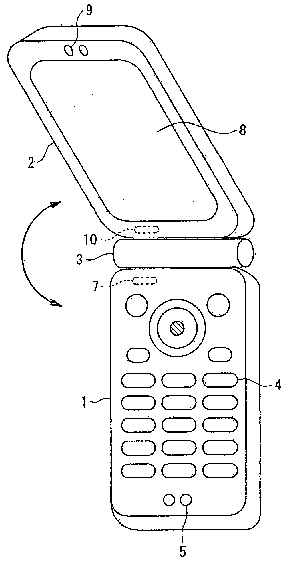
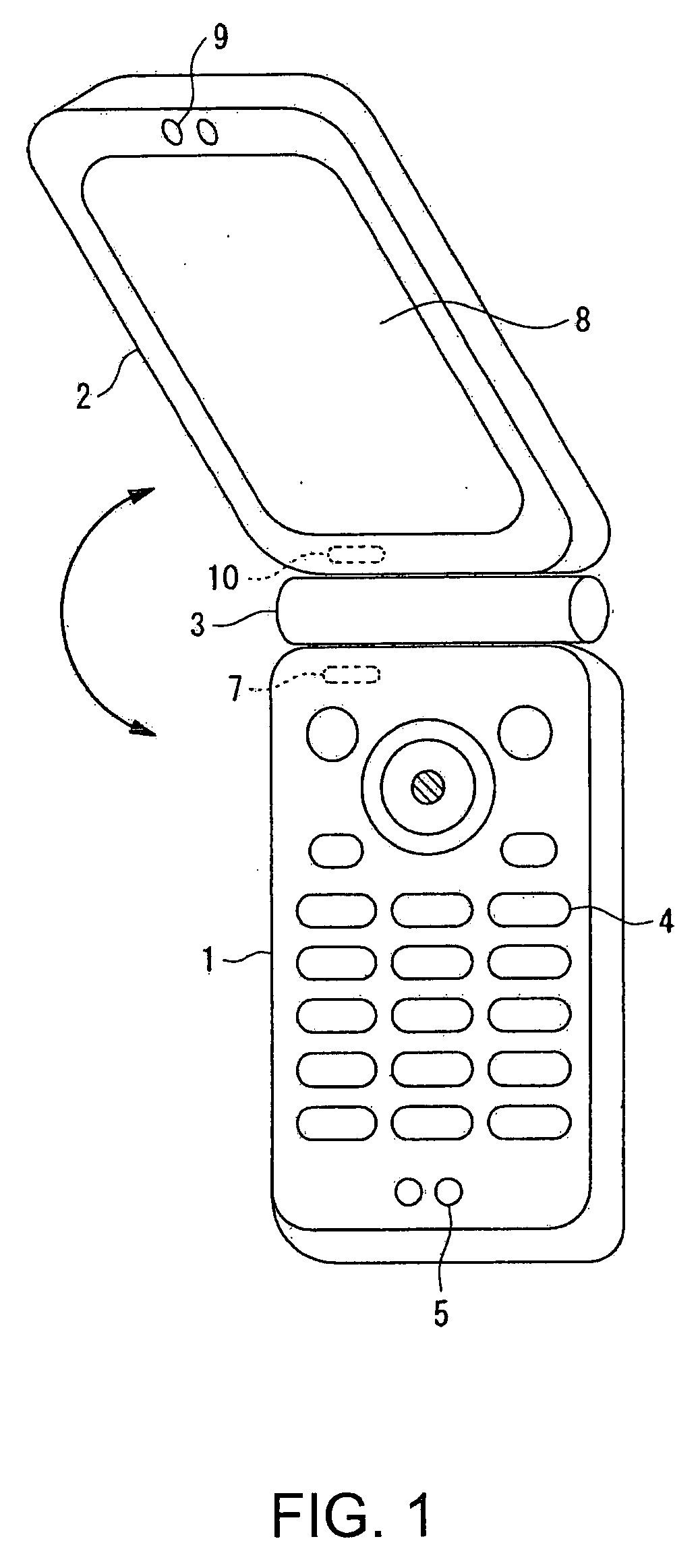
[0014] To attain the above-described advantage, a wireless communication terminal according to one aspect of the invention includes a first case member, a second case member coupled with the first case member, a coupling portion that couples the first and second case members so that the positional relation between the first and second case members can be changed, an external wireless communication antenna provided at the first case member, an external wireless communication control portion that mainly controls external wireless communication carried out through the external wireless communication antenna, a first internal wireless communication antenna, a first internal wireless communication control portion that controls internal wireless communication carried out through the first internal wireless communication antenna, a display part provided at the second case member, a second internal wireless communication antenna, a second internal wireless communication control portion that controls internal wireless communication carried out through the second internal wireless communication antenna, and an output power control portion that controls the output power of waves transmitted by the internal wireless communication antennas based on the timing of transmitting waves transmitted through the external wireless communication antenna.
[0015] In this way, the transmission power of the internal wireless communication carried out between the first and second case members can be controlled depending on the power handled by the external wireless communication. Therefore, while the effect of the internal wireless communication upon the quality of the external wireless communication is reduced, the internal wireless communication can be carried out. If the effect of interference by the external wireless communication is great, the deterioration in the quality of the internal wireless communication can be reduced. Therefore, the communication quality both in the external and internal wireless communication can be secured, while data transmission between the first and second case members can be carried out wirelessly. Consequently, even if the data transmission quantity between the first and second case members increases, the positional relation between the first and second case members can be changed without complicating the structure of the coupling portion. Therefore, the size of the wireless communication terminal can be reduced and the reliability can be improved while an increase in cost is kept low. In addition, the wireless communication terminal may have a larger screen and can carry out an increased number of functions while the portability of the wireless communication terminal is not impaired.
[0016] A wireless communication terminal according to another aspect of the invention includes a first case member, a second case member, a coupling portion that couples the first and second case members so that the positional relation between the first and second case members can be changed, an external wireless communication antenna provided at the first case member, an external wireless communication control portion that mainly controls external wireless communication carried out through the external wireless communication antenna, a first internal wireless communication antenna, a first internal wireless communication control portion that controls internal wireless communication carried out through the first internal wireless communication antenna, a display part provided at the second case member, a second internal wireless communication antenna, a second internal wireless communication control portion that controls internal wireless communication carried out through the second internal wireless communication antenna, a carrier detecting portion that detects the output level of waves transmitted from the external wireless communication antenna, and an output power control portion that controls the output power of waves transmitted from at least one of the first and second internal wireless communication antennas based on the output level detected by the carrier detecting portion.
[0017] In this way, the output level of waves transmitted through the external wireless communication antenna can be directly monitored, and it can be determined whether or not the waves are transmitted through the external wireless communication antenna. Therefore, according to the transmission timing for external wireless communication, the transmission power of the internal wireless communication can be controlled, and the cost can be prevented from increasing, the size of the wireless communication terminal can be reduced, and the reliability of the terminal can be improved. Meanwhile, the screen size at the wireless communication terminal can be increased and the number of functions carried out by the terminal can be increased while the portability of the terminal is not impaired.
[0018] According to another aspect of the invention, the output power control portion sets the transmission power of the internal wireless communication carried out at the time of transmission by the external wireless communication to be larger than the transmission power of the internal wireless communication carried out at the receiving time by the external wireless communication.

Problems solved by technology

Therefore, in a mobile telephone handset with a clamshell design, the flexible wiring board with an increased number of pins must be passed through the hinge to allow the data transmission between the first and second case members through a wire, which complicates the hinge structure or the packaging process.
This is not only an obstacle to reduce the size of the mobile telephone handset, but also pushes up the cost, and the reliability can be lowered.
In this case, the communication suffers from interference with wireless communication outside the mobile telephone.
Therefore, the environment for the internal wireless communication changes depending on the wireless communication outside the mobile telephone, and the reliability in surely transmitting data can be deteriorated.
Therefore, the effect of even a signal outside the band of interest upon the internal wireless communication could not be ignored, the interference with the wireless communication outside the mobile telephone degrades the wireless communication environment, the bit error rate increases and retransmission caused by increase in the packet error rate could be increased.
A complicated and large-scale circuit configuration is necessary, and the cost, size, and weight are increased.

Method used


Image

  • Wireless communication terminal and mobile type wireless communication terminal
  • Wireless communication terminal and mobile type wireless communication terminal
  • Wireless communication terminal and mobile type wireless communication terminal

Examples


first embodiment

[0052]FIG. 4 is a schematic block diagram of a wireless communication terminal according to the invention.

[0053] In FIG. 4, a first case member K11 includes an external wireless communication antenna 101 that transmits / receives waves for external wireless communication, a radio frequency processing portion 102 that modulates / demodulates a signal transmitted / received through the external wireless communication antenna 101, a base band signal processing portion 103 that carries out base band signal processing, a control portion 104 that controls the wireless communication terminal as a whole, a RAM 105 that provides the control portion 104 with a work area for carrying out processing and storing the result of processing, a ROM 106 that stores various control programs used to operate the wireless communication terminal, a transmitting / receiving portion 107 that controls the internal wireless communication carried out through the internal wireless communication antenna 108, an internal ...

second embodiment

[0076]FIG. 8 is a schematic block diagram of the configuration of a wireless communication terminal according to the invention.

[0077] In FIG. 8, a first case member K31 includes an external wireless communication antenna 301, a radio frequency processing portion 302, a base band signal processing portion 303, a control portion 304, a RAM 305, a ROM 306, a transmitting / receiving portion 307, an internal wireless communication antenna 308, a carrier detecting portion 309, an power control portion 310, and a carrier detecting antenna 311. A second case member K32 includes a transmitting / receiving portion 321, an internal wireless communication antenna 322, a camera 323, a liquid crystal display part 324, and an additional device 325. The first and second case members K31 and 32 are hinged together so that their positional relation can be changed.

[0078] Waves transmitted through the external wireless communication antenna 301 are received by the carrier detecting antenna 311, and the c...

third embodiment

[0081]FIG. 9 is a schematic block diagram of the configuration of a wireless communication terminal according to the invention.

[0082] In FIG. 9, A first case member K41 includes an external wireless communication antenna 401, a radio frequency processing portion 402, a base band signal processing portion 403, a control portion 404, a RAM 405, a ROM 406, a transmitting / receiving portion 407, an internal wireless communication antenna 408, and a power control portion 410. A second case member K42 includes a transmitting / receiving portion 421, an internal wireless communication antenna 422, a camera 423, a liquid crystal display part 424, and an additional device 425. The first and second case members K41 and K42 are coupled so that their positional relation can be changed.

[0083] When data is transmitted through the external wireless communication antenna 401, the control portion 404 transmits transmission data to the base band signal processing portion 403 and notifies the power cont...


PUM


Abstract

A wireless communication terminal includes first and second case members coupled together by a coupling portion so that the positional relation therebetween can be changed, an external wireless communication antenna provided at the first case member, an external wireless communication control portion mainly controlling external wireless communication carried out through the external wireless communication antenna, a first internal wireless communication antenna, a first internal wireless communication control portion controlling internal wireless communication carried out through the first internal wireless communication antenna, a display part provided at the second case member, a second internal wireless communication antenna, a second internal wireless communication control portion controlling internal wireless communication carried out through the second internal wireless communication antenna, and an output power control portion controlling the output power of waves transmitted by the internal wireless communication based on the timing of transmitting waves transmitted through the external wireless communication antenna.

Description

RELATED APPLICATIONS [0001] This application is a divisional patent application of U.S. Ser. No. 11 / 159,045 filed Jun. 22, 2005 and claims priority to Japanese Patent Application No. 2004-188349 filed Jun. 25, 2004 which is hereby expressly incorporated by reference herein in its entirety.BACKGROUND OF THE INVENTION [0002] 1. Technical Field [0003] The present invention relates to a wireless type communication terminal and a mobile type wireless communication terminal, and is particularly applicable to a clamshell type mobile telephone and the like. [0004] 2. Related Art [0005] In recent years, there have been attempts to increase the resolution of liquid crystal displays in the mobile telephones so that still pictures or moving images taken by the digital cameras can be displayed with higher definition in addition to normal still images such as characters and graphics. This increases data quantities exchanged between a digital camera and a liquid crystal display and the use of LVDS...

Claims


Application Information

Patent Timeline
Patent Type & Authority Applications(United States)
IPC IPC(8): H04M1/00H04M1/02
CPCH04M1/0214Y02B60/50H04M1/0225
Inventor IRIE, MICHIO
Owner SEIKO EPSON CORP
Learn More