Handle for Multifunction Endoscope

a multi-functional, endoscope technology, applied in the field of endoscopes, can solve the problems of increasing the complexity of the presence of tubes, lines, wires, etc., and achieve the effect of increasing the complexity of the procedure and complicated design of the proximal portion of the endoscop

Inactive Publication Date: 2007-11-22
AMS RES CORP
View PDF18 Cites 109 Cited by
  • Summary
  • Abstract
  • Description
  • Claims
  • Application Information

AI Technical Summary

Benefits of technology

[0011]A simple endoscope used for examination of an organ may have only two ports, one for the light source and one for the optical image. However, endoscopes used for medical procedures such as ablation of tissue using laser energy will typically have many more ports and therefore make the design of the proximal portion of the endoscope more complicated. The increased complexity includes the presence of tubes, lines, wires and other things extending from the proximal portion of the endoscope. One aspect of the invention is the recognition that different individuals using the same endoscope will often hold and manipulate the endoscope by its proximal portion in different ways. This is particularly true for multifunction endoscopes used for both of viewing and for treatment, at least in part because of the increased complexity of the procedure and the number of things extending from the proximal portion, as well as the personal preferences of the operator.

Problems solved by technology

However, endoscopes used for medical procedures such as ablation of tissue using laser energy will typically have many more ports and therefore make the design of the proximal portion of the endoscope more complicated.
The increased complexity includes the presence of tubes, lines, wires and other things extending from the proximal portion of the endoscope.
This is particularly true for multifunction endoscopes used for both of viewing and for treatment, at least in part because of the increased complexity of the procedure and the number of things extending from the proximal portion, as well as the personal preferences of the operator.

Method used


Image

  • Handle for Multifunction Endoscope
  • Handle for Multifunction Endoscope
  • Handle for Multifunction Endoscope

Examples


Embodiment Construction

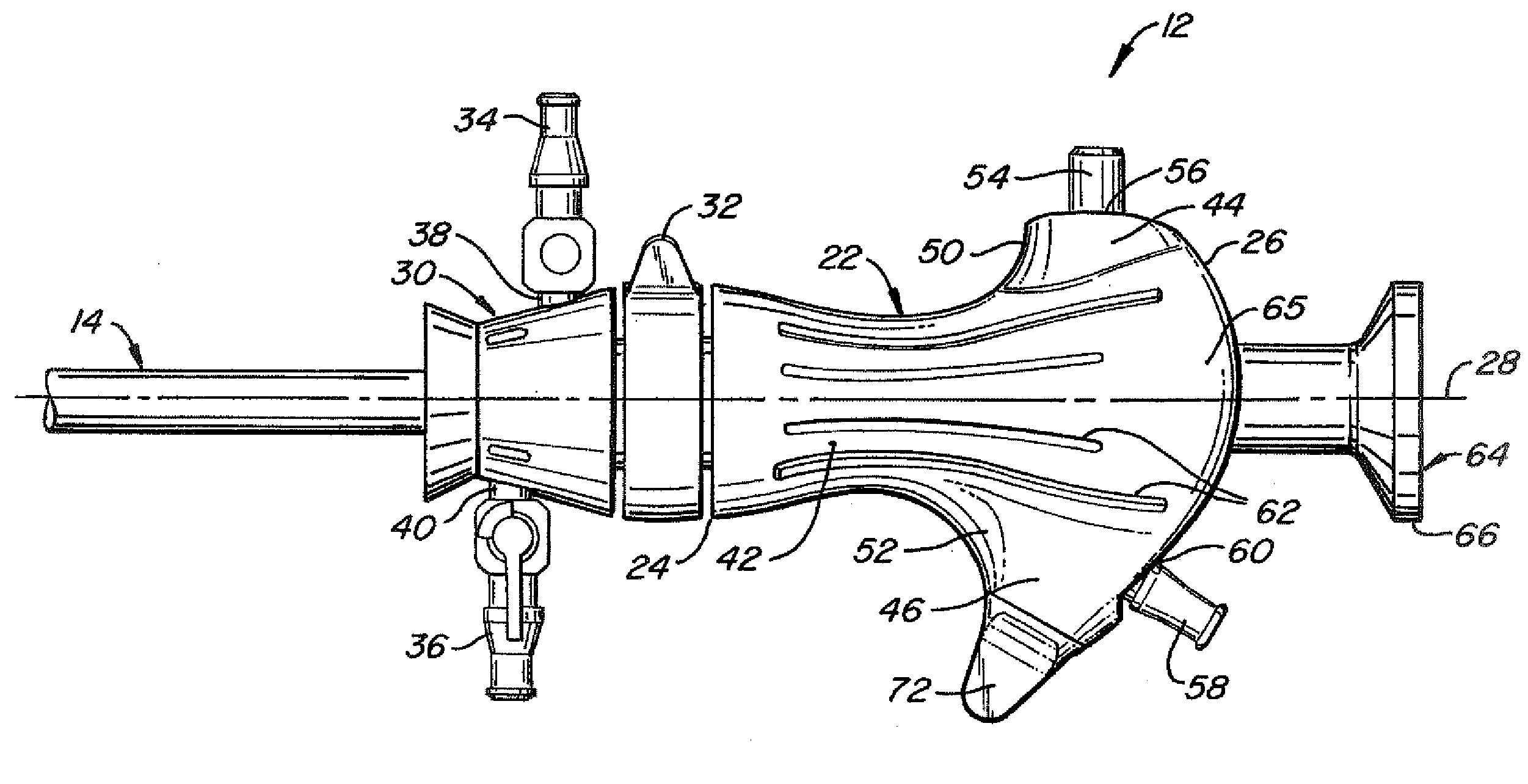
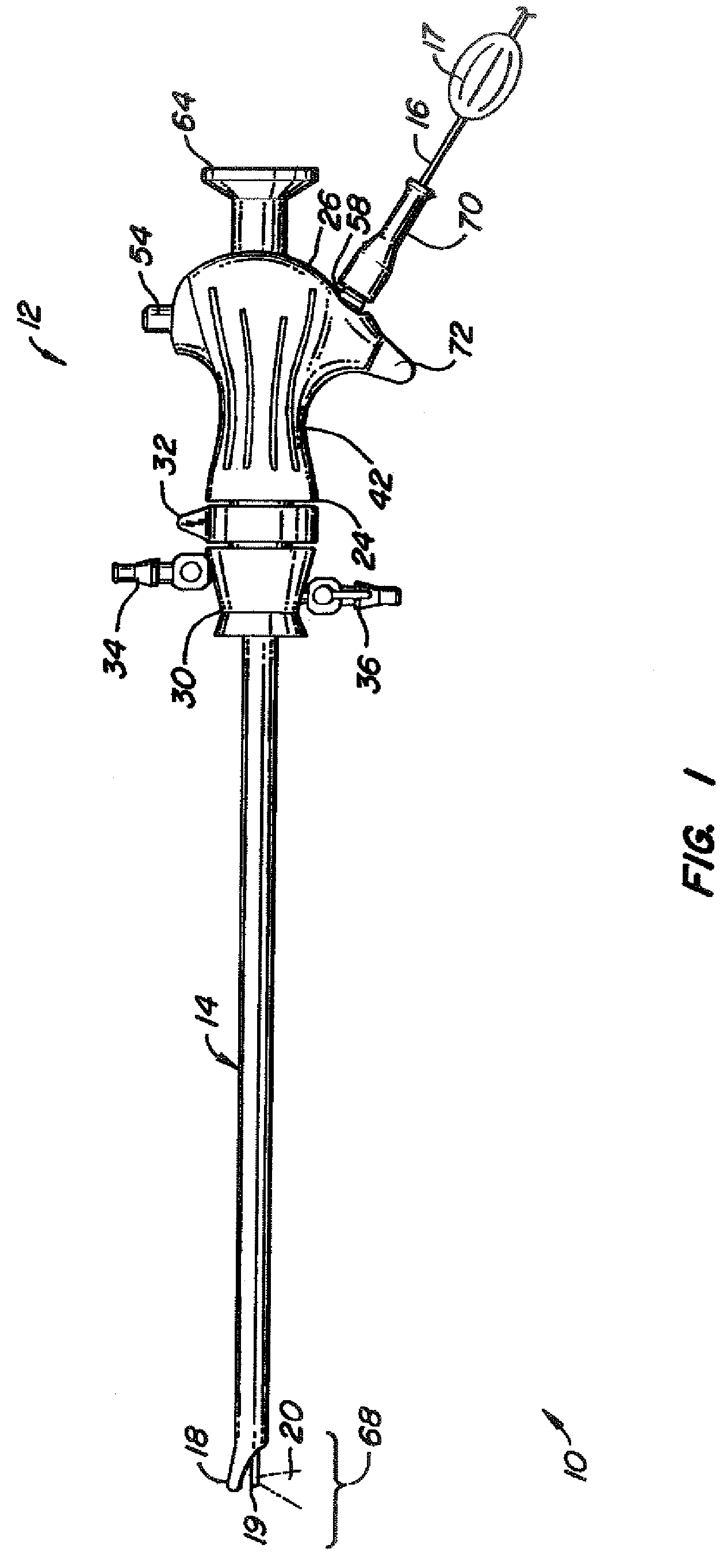
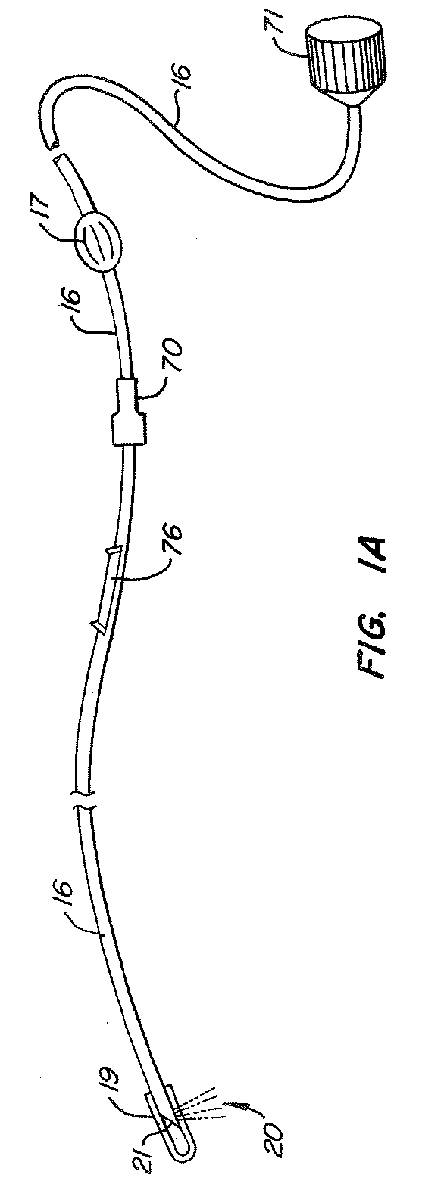
[0029]FIG. 1 illustrates a multifunction endoscope 10, such as a transurethral cystoscope, including a handle 12 with an external cannula 14 extending distally from the handle 12. In this embodiment multifunction endoscope 10 is designed for use with a medical laser device of the type including an optical fiber 16 having a fiber end member 19 which extends into a cavity formed by a hood structure (described in more detail below and in Provisional Patent Application No. 60 / 747,780, the disclosure of which is incorporated by reference) on the distal tip 18 of external cannula 14. The optical fiber 16 has a fiber manipulator knob 17 attached near the handle 12, that is adapted to be used by a surgeon to manipulate the position of the fiber end member, rotationally and longitudinally. External cannula 14 has a number of passageways or lumens formed by an internal structure, not shown, extending generally from handle 12 to distal tip 18 to accommodate, in this disclosed embodiment, optic...


PUM


Abstract

A multifunction endoscope handle comprises a body cover, a first body cover extension and a second body cover extension. The body cover comprises distal and proximal ends with a waist of therebetween. The proximal and distal end circumferences part each larger than the waist circumference. The body cover also comprises an outer surface tapering from the distal and proximal ends to the waist. Both of the first and second body cover extensions extend radially outwardly directions from the outer surface of the body cover. In some embodiments the proximal circumference is larger than the distal circumference. The outer surface is preferably a smoothly tapering outer surface. The body cover may comprise a plurality of ports at a proximal portion thereof.

Description

CROSS-REFERENCE TO RELATED APPLICATION[0001]This application claims the benefit of Provisional Patent Application No. 60 / 747,780 filed 19 May 2006, entitled Endoscope for Fiber Optic Procedures, Attorney Docket LSCP 1026-1.BACKGROUND OF THE INVENTION[0002]1. Field of the Invention[0003]The present invention relates generally to endoscopes, and in particular the configuration of a handle used for a multifunction endoscope.[0004]2. Description of Related Art[0005]An endoscope is an illuminated medical device used look inside the body and examine organs. An endoscope can be rigid or flexible. Endoscopes designed for particular procedures often have specialized names, such as cystoscope (bladder), nephroscope (kidney), bronchoscope (bronchi), laryngoscope (larynx), otoscope (ear), arthroscope (joint) and laparoscope (abdomen). In addition to being used for viewing and examination, endoscopes are often used with various types of medical instruments for diagnostic and therapeutic procedur...

Claims


Application Information

Patent Timeline
Patent Type & Authority Applications(United States)
IPC IPC(8): A61B1/00
CPCA61B1/015A61B1/018A61B1/07A61B1/0017A61B2018/2272A61B2019/304A61B2019/305A61B18/24A61B2090/034A61B2090/035
Inventor NAHEN, KESTERARNOLD, KENSTINSON, DOUGLAS G.ASTURIAS, EDUARDOLAZZARO, VICTORKERMODE, JAMES RAYMOND
Owner AMS RES CORP
Why Eureka
Try Eureka