Human bone substitutional implant

a bone substitute and implant technology, applied in the field of human bone substituted implants, can solve the problems of reducing joint strength, affecting the quality of bone replacement, and causing large heat generation

Inactive Publication Date: 2007-11-22
WU SHING SHENG
View PDF14 Cites 142 Cited by
  • Summary
  • Abstract
  • Description
  • Claims
  • Application Information

AI Technical Summary

Problems solved by technology

But its bio-compatibility is bad.
It combines with human bone in a non-bone way, and will cause unsettlement of the connection portion at a later stage of use, hence reducing the joint strength.
A large amount of heat will be produced when PMMA bone cement solidifies and hardens.
Moreover, because PMMA bone cement will decompose into poisonous units, it is very harmful to the human body.
Therefore, the use of PMMA bone cement in surgery is restricted.
Although the problem that bone cement material has a high risk of bio-exclusion has been continually improved, it still has other problems to be solved urgently.
Once the hip joint is problematic, one will has the problem in walking or even lose his working capability.
The necrosis speed of the femoral head may be very slow or very high.
The above methods, however, have little effects for some people.
Although the initial effect is good, side effects to the human body will easily arise for a long time use of drug.
Without a healthy knee joint, one's capability of activity will be much limited or he even has a big problem in every step of walking.
Therefore, longtime bad posture, bearing a heavy burden or a too high weight will lead to damage of the cartilage of the knee and slight displacement of the joint, hence increasing abrasion and destruction of the cartilage on the surface of the knee joint.
If the knee joint abrades excessively and can't do well for walking and the X-ray photograph shows there is no gap between the joints, it means the cartilage of the joint is severely abraded and destructed.
Although the knee joint replacement surgery is more and more popular, there are still some patients whose bones of the knee joint are damaged or have the problem of avascular necrosis so that the artificial knee bone surgery is of no use to them.

Method used


Image

  • Human bone substitutional implant
  • Human bone substitutional implant
  • Human bone substitutional implant

Examples


Embodiment Construction

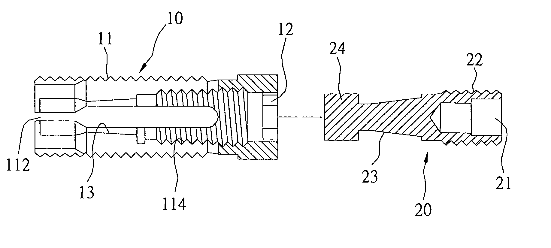
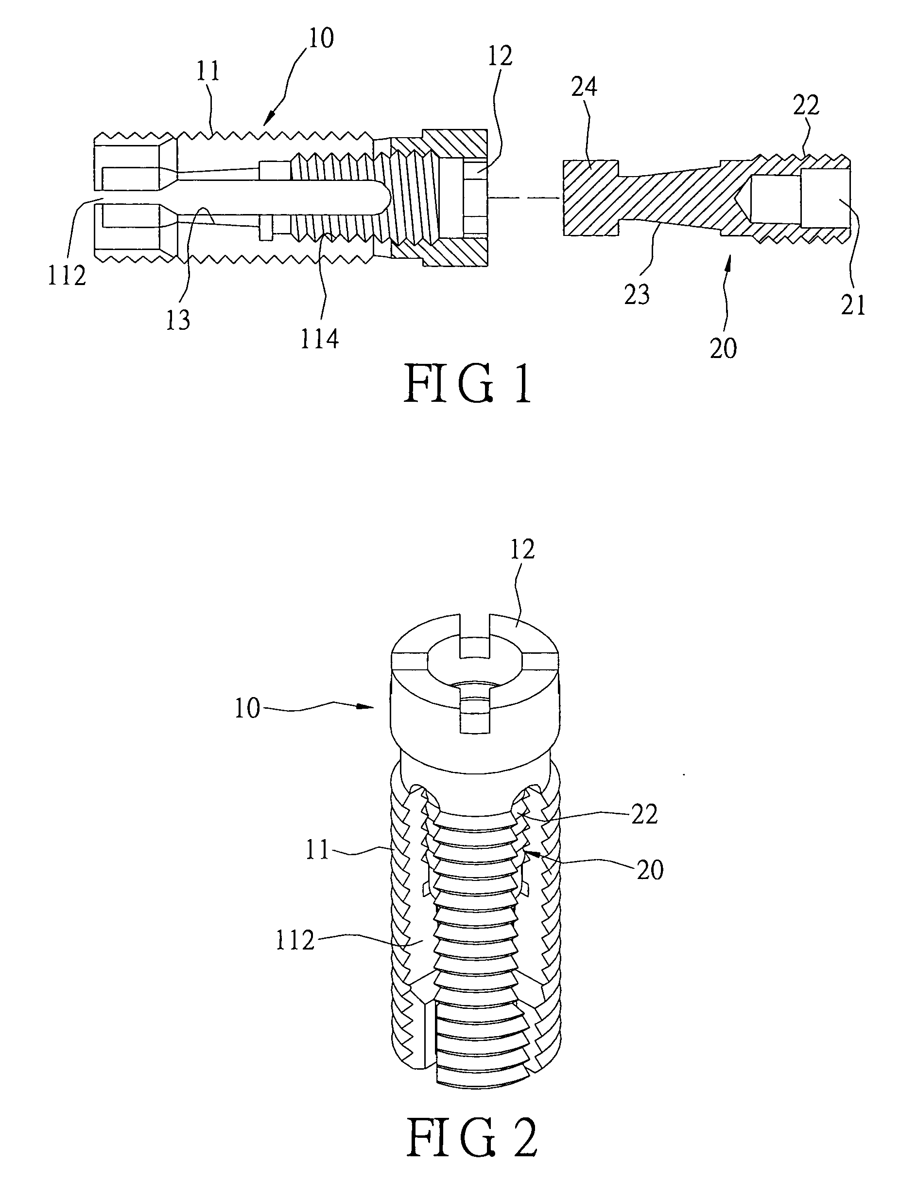
[0025] As shown in FIGS. 1 and 2, the present invention provides a human bone substitutional implant, which comprises a main body 10 and a push body 20. The main body 10 is a hollow circular cylinder (or a square cylinder shown in FIG. 6). A conical passage 13 is formed in the main body 10. The diameter of the conical passage 13 gradually diminishes towards the front end of the main body 10. A thread portion 11 (or a ratchet portion 14 shown in FIG. 6) is disposed on an end of the outer wall of the main body 10. The original outer wall is reserved at the other end. A fixing portion 12 is disposed on this other end face and has a groove. The groove is of a straight line shape, a cross shape, a square shape, or a hexagon shape. The thread portion 11 (or the ratchet portion 14) is divided into four equal parts by slits 112. An inner thread 114 is disposed on the inner wall of the main body 10.

[0026] One end face of the push body 20 has another groove 21. This groove 21 is of a square ...


PUM


Abstract

A human bone substitutional implant comprises a main body and a push body. The main body is a hollow cylinder with a thread portion or a ratchet portion disposed on its outer wall. The thread portion or the ratchet portion has at least a slit dividing it into four equal parts. An inner thread is disposed on the inner wall of the thread portion or the ratchet portion. An outer thread is disposed on the outer surface of the push body and corresponds to the inner thread. The push body and the main body are joined together via screw connection of the outer thread and the inner thread. Because the main body has a conical passage therein, the main body will be held open a certain angle to support and enhance a fractured bone of the human body when the push body is axially pushed into the main body.

Description

BACKGROUND OF THE INVENTION [0001] 1. Field of the Invention [0002] The present invention relates to a human bone substitutional implant and, more particularly, to a substitutional implant used for supporting and enhancing a spine, a hip joint or a knee joint of the human body. [0003] 2. Description of Related Art [0004] In order to cure spine fracture caused by osteoporosis or external forces, a substitutional implant capable of replacing the fractured spine is usually used. The substitutional implant most commonly used by surgeons in spine surgery is PMMA bone cement, which is the material for replacing the fractured spine at the initial stage. [0005] PMMA bone cement is easily shaped and convenient for use. But its bio-compatibility is bad. It combines with human bone in a non-bone way, and will cause unsettlement of the connection portion at a later stage of use, hence reducing the joint strength. Besides, PMMA bone cement does not solidify and harden by itself so that a solidif...

Claims


Application Information

Patent Timeline
Patent Type & Authority Applications(United States)
IPC IPC(8): A61F2/44
CPCA61B17/70A61F2002/30579A61F2/44A61B17/8858
Inventor WU, SHING-SHENG
Owner WU SHING SHENG
Why Eureka
Try Eureka