Corner painting roller sytem

a technology of rollers and corners, applied in the direction of portable power tools, manufacturing tools, carpet cleaners, etc., can solve the problems of slow and tedious process, inability to apply surface coatings into deep corners, and limit the application of corners with brushes or painting pads, etc., to achieve great ease and speed

Inactive Publication Date: 2007-11-29
DOUGLAS RUSSELL
View PDF10 Cites 0 Cited by
  • Summary
  • Abstract
  • Description
  • Claims
  • Application Information

AI Technical Summary

Benefits of technology

[0013]The system includes a corner-roller cover and an adapter. The corner-roller cover is designed to rapidly deliver coatings to corners where two or more surfaces come together, resulting in the complete covering of the space with an even-coating. The adapter works in conjunction with a conventional paint pan, and aids in loading the corner-roller cover with the surface coating (paint, etc.). Once the corner-roller cover is loaded with the surface coating material, the coating can be applied to the corner with great ease and speed.

Problems solved by technology

While these rollers work well on flat surfaces, they cannot be used to apply surface coatings into deep corners where two or more surfaces meet.
To overcome this limitation of conventional rollers or covers, corners had been coated using a brush or paint pad, which is a slow and tedious process.
In painting a room with conventional rollers, painting of corners with a brush or painting pad is the limiting factor in the expeditious completion of the job.
This assembly requires the use of wrenches, which are not always readily available during a coating operation, and which occasionally fail to work properly.
This results in a difficult and messy disassembly of these rollers, with fouling of hands and wrenches with the coating material.
This inevitably leads to marring of the wall finish, messy cleanups, and optionally messy and time consuming reattachments of the paint fabric to the roller cover body.
These problems are exacerbated when the roller is used quickly.
Adequately sized painting accessories cannot fit into a paint can unless the roller is too small to be useful, because there would not be sufficient room to properly load the roller with paint.

Method used


Image

  • Corner painting roller sytem
  • Corner painting roller sytem
  • Corner painting roller sytem

Examples


Embodiment Construction

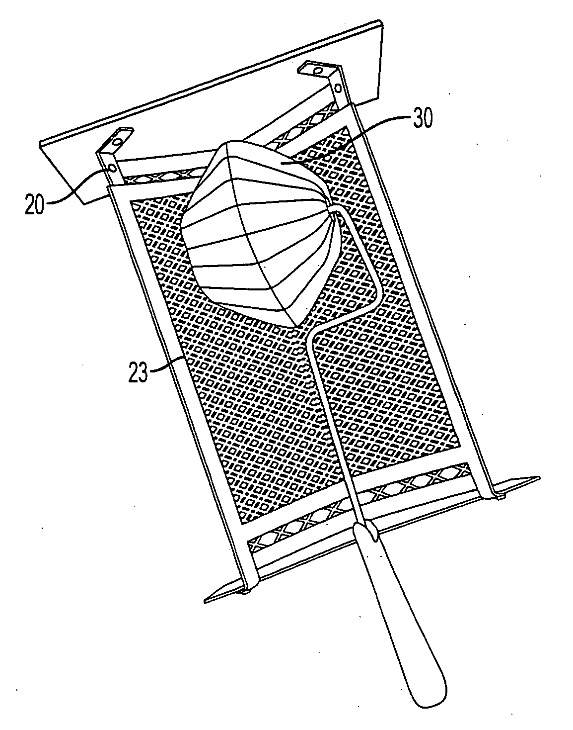
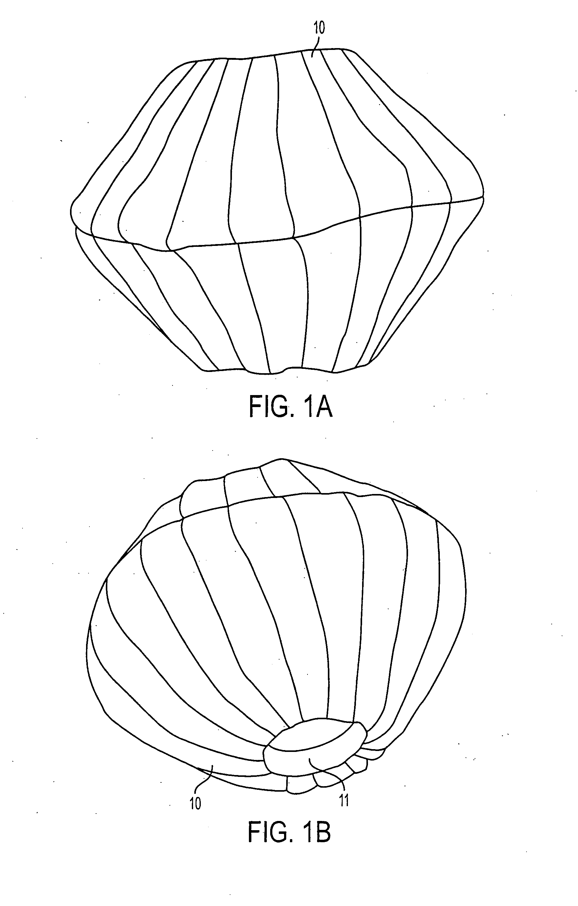
[0026]FIG. 1A shows a top view of a covered spindle-shaped corner-roller cover 10. FIG. 1B shows a side view of the spindle-shaped covered corner-roller cover 10, and hole 11 through its side. The hole 11 can be any diameter to accommodate a wire roller. However, for a conventional wire roller four inches long, the diameter of the hole 11 is about 1.5 inches. The spindle-shaped cover is attached to the wire roller by inserting the roller into the hole 11 of the cover. The roller cover body 80 is made of a hollow rigid material (FIG. 8) which is then covered with a material that can hold coating material for application therefrom, as shown in FIGS. 1A and 1B. This spindle-shaped body can be made of any rigid material which will permit the attachment of fabric or paint absorbing material to its outer surface. Use of a plastic for the body makes the roller cover strong, lightweight and inexpensive to produce, although any suitable rigid material can be used for the spindle-shaped body....


PUM


Abstract

A system for applying liquid coating to a surface comprises a spindle-shaped roller cover and an adapter. The adapter is provided with a V-shaped grille against which the roller cover rolls to pick up coating material from a reservoir and to remove excess coating material from the roller cover.

Description

FIELD OF THE INVENTION [0001]The present invention relates to a system for applying surface coatings to areas where two or more surfaces join-each other, such as corners.BACKGROUND OF THE INVENTION [0002]Conventional paint rollers are composed of two parts: a wire roller that freely spins on an axle as the roller move across a-surface, and a roller cover, a fabric-covered cylinder which slips onto the wire roller. The wire roller has a handle for the user to grasp. When attached to the wire roller, the roller cover is made to absorb paint from a reservoir, such as a paint pan. This absorbed paint is then applied to a surface by a rolling action. Currently, applicators of liquid surface coating materials such as paints use a fabric covered roller to rapidly apply these coatings to surfaces. While these rollers work well on flat surfaces, they cannot be used to apply surface coatings into deep corners where two or more surfaces meet. These deep corners occur, for example, in a room wh...

Claims


Application Information

Patent Timeline
Patent Type & Authority Applications(United States)
IPC IPC(8): B05C17/02
CPCB05C17/0212B44D3/128B05C17/0245
Inventor DOUGLAS, RUSSELL
Owner DOUGLAS RUSSELL
Why Eureka
Try Eureka