Gas turbine having cooling-air transfer system

a technology of gas turbine and cooling air, which is applied in the direction of sustainable transportation, mechanical equipment, machines/engines, etc., can solve the problems of high manufacturing cost, complicated structure of nozzles, and limitation of the installation of blade-type tobi nozzles, etc., and achieves convenient attachment and removal. , the effect of easy maintenan

Inactive Publication Date: 2007-11-29
MITSUBISHI HEAVY IND LTD
View PDF17 Cites 17 Cited by
  • Summary
  • Abstract
  • Description
  • Claims
  • Application Information

AI Technical Summary

Benefits of technology

[0013] In order to overcome the above-described problems, the present invention provides a gas turbine equipped with a compact and low-cost cooling-air transfer system having a simple structure.
[0015] In this case, since TOBI nozzles having a simpler structure than blade-type TOBI nozzles can be adopted, the cost of the system is reduced. Moreover, since the cooling air can be easily swirled, pumping loss is reduced and the efficiency of the gas turbine is enhanced.
[0017] In this case, since the jet flow of the cooling air ejected from the tubular nozzle is not damped, pumping loss is reduced.
[0019] In this case, since the optimal nozzle bore can be selected, the total efficiency of the gas turbine is enhanced.
[0021] In this case, the cooling air flow reaches the seal-disk cooling conduit without decreasing the center velocity thereof. Therefore, the cooling air flow can be smoothly transferred in the seal-disk cooling conduit, and this reduces pumping loss.
[0023] In this case, since the nozzle body and the nozzle tip can be easily attached and detached, easy maintenance is possible.

Problems solved by technology

However, the blade-type TOBI nozzles have a complicated structure, and the manufacturing cost thereof is high.
Further, there is a limitation to the installation of the blade-type TOBI nozzles because the TOBI nozzles are installed in the bleeding chamber 43 serving as a narrow annular space provided inside the chamber 42 and surrounded by the partition 48 and the rotor 41.
On the other hand, the tube-type TOBI nozzles disclosed in Japanese Unexamined Patent Application Publication No. 2004-003493 cannot form an effective swirling flow, and pumping loss is increased.

Method used


Image

  • Gas turbine having cooling-air transfer system
  • Gas turbine having cooling-air transfer system
  • Gas turbine having cooling-air transfer system

Examples


Embodiment Construction

[0035] While an embodiment of the present invention will be described with reference to the drawings, it is to be understood that the embodiment is just exemplary and does not limit the scope of the invention. Components similar to those in the related arts are denoted by the same reference numerals, and detailed descriptions thereof are omitted.

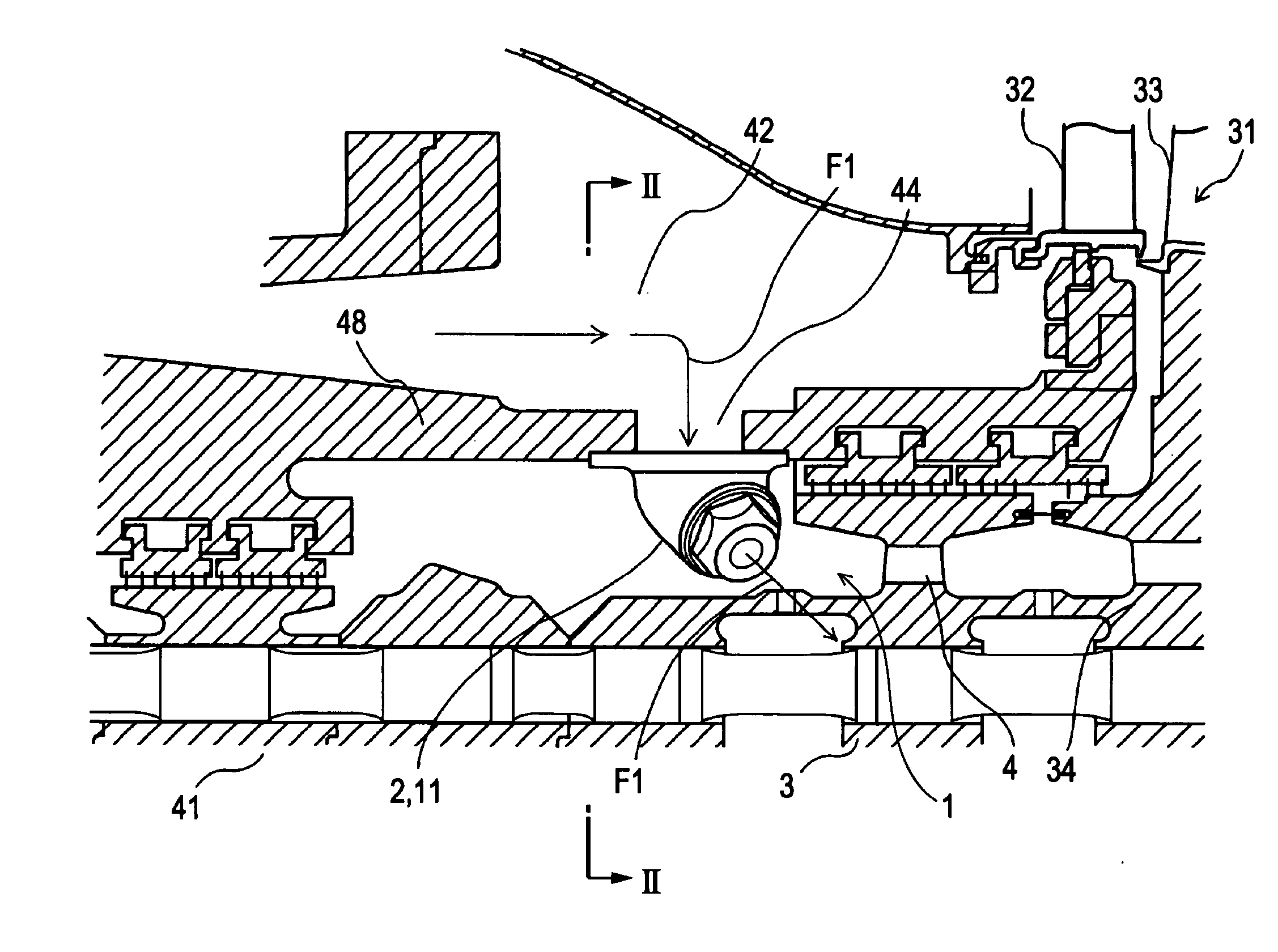
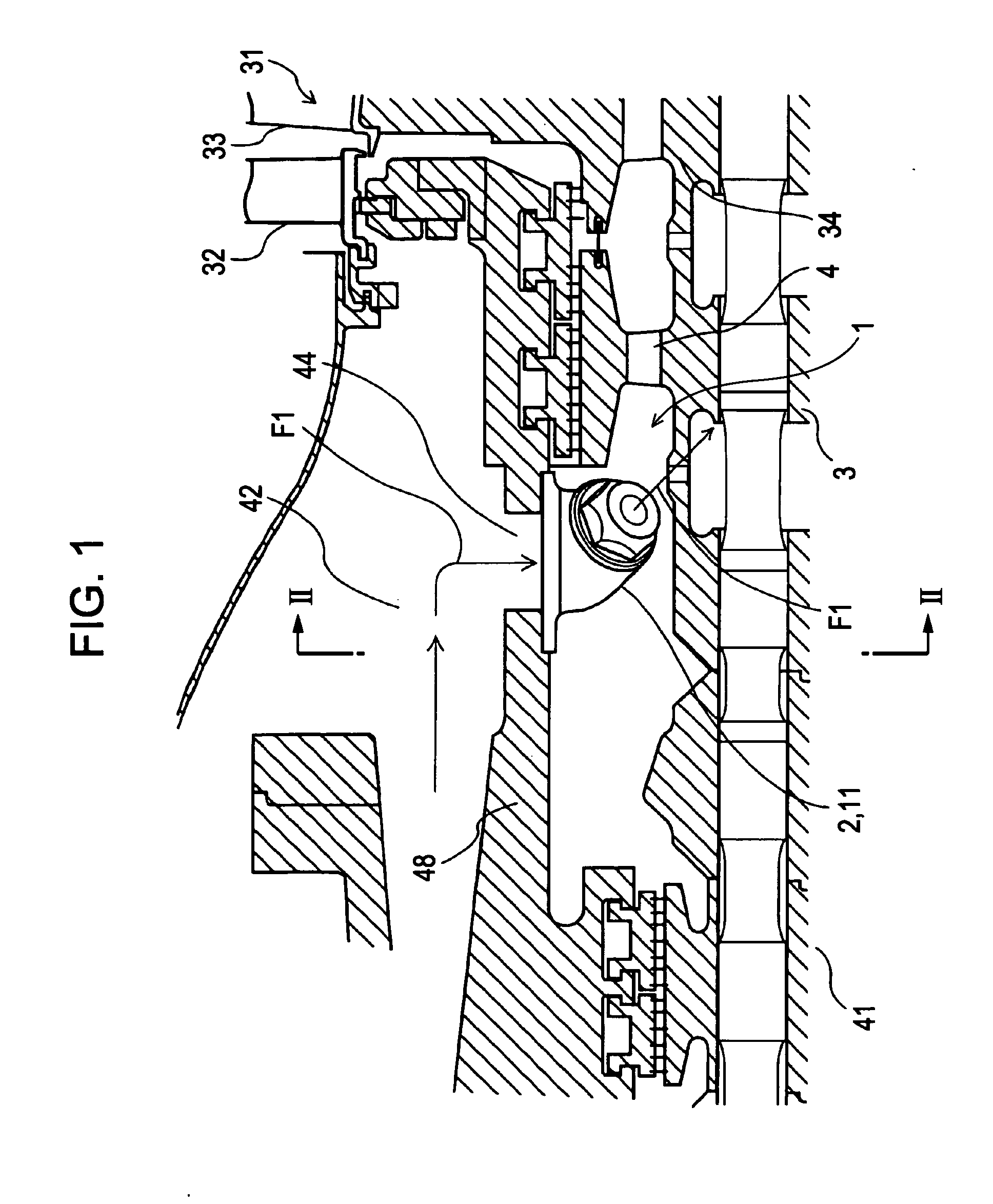
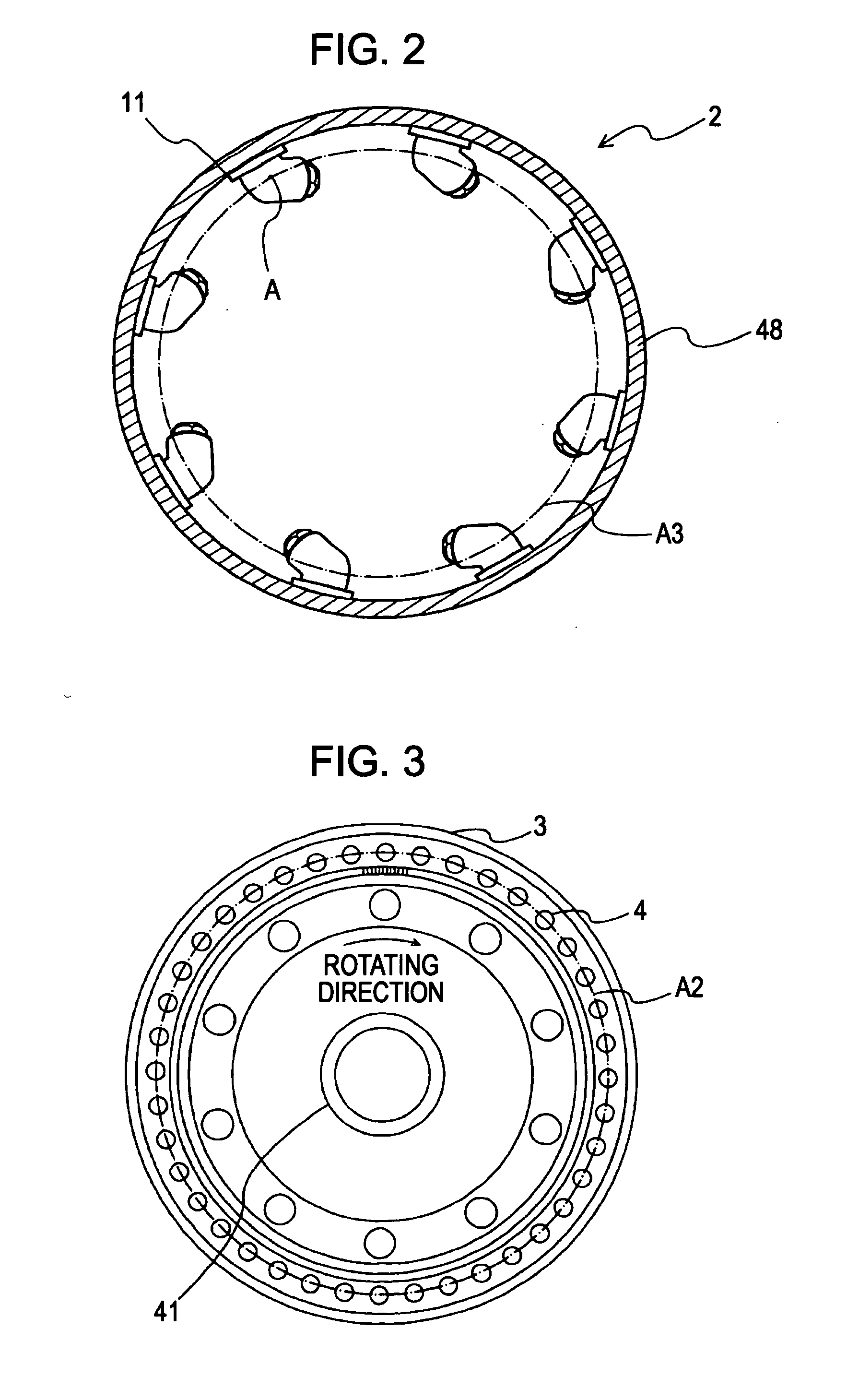
[0036] First, a gas turbine including a cooling-air transfer system according to the present invention will be described below. The concept of a gas turbine including a compressor, a combustor, and a turbine has been given in the description of the background of the invention, and therefore, a description thereof is omitted. Referring to FIG. 1, a cooling-air transfer system 1 serving as the core of the invention includes a group 2 of a plurality of tubular nozzles 11 provided on an inner surface of a partition 48 inside a chamber 42 that stores air discharged from the compressor, and a seal disk 3 provided downstream from and adjacently to...


PUM


Abstract

A gas turbine includes a cooling-air transfer system. The cooing-air transfer system extracts part of air discharged from a compressor to a chamber, and transfers the part of air as cooling air to a rotor disk. The cooling-air transfer system includes a plurality of tubular nozzles independently arranged in a circle inside the chamber to surround a rotor, and a seal disk having seal-disk cooling conduits arranged in a circle around the axis of the rotor so as to receive cooling air ejected from the tubular nozzles. The cooling-air transfer system swirls the cooling air ejected from the tubular nozzles.

Description

BACKGROUND OF THE INVENTION [0001] 1. Field of the Invention [0002] The present invention relates to a gas turbine having a cooling-air transfer system for air that cools moving blades. [0003] 2. Description of the Related Art [0004]FIG. 10 is a conceptual view showing the general configuration of a gas turbine, and FIG. 11 is a structural view of a cooling-air transfer system and its surroundings in a known type of gas turbine. [0005] In a gas turbine, air compressed by a compressor 51 is fed into a combustor 52, combustion gas is produced by combustion after mixing fuel in the compressed air, and is fed into a turbine 53 to rotate the turbine 53, and power is obtained from a power generator 54 by the rotation of the turbine 53, as shown in FIG. 10. Since the temperature of the produced combustion gas is high, it is necessary to cool moving blades and stationary blades. For that purpose, commonly, part of cooling air is extracted from a chamber that is provided on a discharging sid...

Claims


Application Information

Patent Timeline
Patent Type & Authority Applications(United States)
IPC IPC(8): F02C7/12
CPCF01D5/06F01D5/082Y02T50/676F01D5/085F01D5/084Y02T50/60
Inventor TAKAOKA, YOSHIMASAARAKI, MASATOLAURELLO, VINCENTKATAOKA, MASAHITOMASADA, JUNICHIROISHIZAKA, KOICHIHAGI, NAOKI
Owner MITSUBISHI HEAVY IND LTD
Why Eureka
Try Eureka