

Heat sink
a heat sink and heat sink technology, applied in the field of heat sinks, can solve the problems of reducing cooling efficiency, difficult to bend a flat plate-shaped heat pipe, and wicks may be cut when
- Summary
- Abstract
- Description
- Claims
- Application Information
AI Technical Summary
Benefits of technology
Problems solved by technology
Method used
Image

Examples
first embodiment
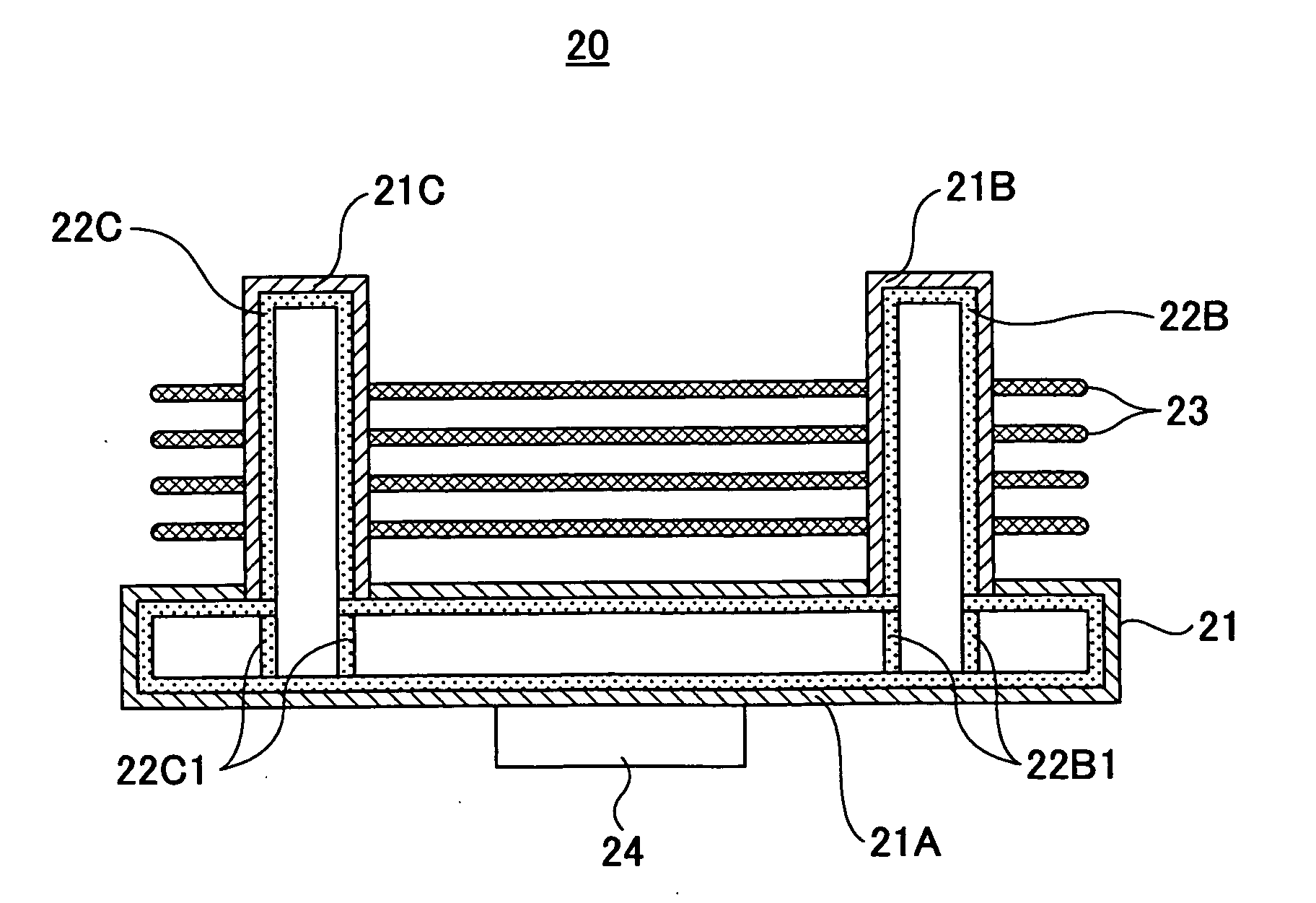
[0048]FIG. 6A is a plan view of a heat sink according to a FIG. 6B is a cross-sectional view of the heat sink shown in FIG. 6A. The heat sink shown in FIGS. 6A and 6B has a three-dimensional structure in which plate-shaped heat pipes 21B and 21C are perpendicularly connected to a plate-shaped heat pipe 21A. A plurality of heat-radiating fins 23 are attached parallel to the heat pipe 21A so as to bridge between the heat pipes 21B and 21C. The wick 22A in the heat pipe 21A and the wicks 22B and 22C in the heat pipes 21B and 21C are connected according to the connection structure explained with reference to FIG. 2 through FIG. 5. In the present embodiment, a center portion serving as a heat-receiving part of the heat pipe 21A is joined to a semiconductor device 24 as a heat-generating member so that the heat sink 20 serves as a cooling device for cooling the semiconductor device 24.
second embodiment
[0049]FIG. 7 is a cross-sectional view of a heat sink according to a The heat sink shown in FIG. 7 has a three-dimensional structure in which heat pipes 31B and 31C are connected to opposite ends of a heat pipe 31A. A plurality of heat-radiating fins 33 are attached parallel to the heat pipe 31A to bridge between the heat pipe 31B and 31C. A wick 32A in the heat pipe 31A and inner-side portions of wicks 32B and 32C in the heat pipes 31B and 31C are connected according to the connection structure explained with reference to FIG. 2 through FIG. 5. In the present embodiment, a center portion serving as a heat-receiving part of the heat pipe 31A is joined to a semiconductor device 24 as a heat-generating member so that the heat sink 30 serves as a cooling device for cooling the semiconductor device 24.
third embodiment
[0050]FIG. 8 is a cross-sectional view of a heat sink according to a The heat sink 40 shown in FIG. 8 has the same structure as the heat sink 20 shown in FIGS. 6A and 6B except for heat-radiating fins 44 attached perpendicularly to a heat pipe 41A. That is, the heat sink shown in FIG. 8 has a three-dimensional structure in which heat pipes 41B and 41C are connected to opposite ends of the heat pipe 41A. A plurality of heat-radiating fins 43 are attached parallel to the heat pipe 41A to bridge between the heat pipe 41B and 41C. A wick 42A in the heat pipe 41A and the wicks 42B and 42C in the heat pipes 41B and 41C are connected according to the connection structure explained with reference to FIG. 2 through FIG. 5. In the present embodiment, a center portion serving as a heat-receiving part of the heat pipe 41A is joined to a semiconductor device 24 as a heat-generating member so that the heat sink 40 serves as a cooling device for cooling the semiconductor device 24.
PUM
 Abstract
Description
Claims
Application Information