System for interphase control at an electrode/electrolyte boundary

a technology of interphase control and electrode, applied in the field of electrolytic cells, can solve the problems of nelson not addressing the inductance of the electrochemical cell itself, the inability of prior art apparatus to provide precise manipulation of the interphase, and the inability to manufactur

Inactive Publication Date: 2007-11-29
MATTHEWS MEHLIN DEAN
View PDF5 Cites 20 Cited by
  • Summary
  • Abstract
  • Description
  • Claims
  • Application Information

AI Technical Summary

Benefits of technology

[0028]In still a further embodiment the switched current supply is capable of providing pulses at three or more potential levels.

Problems solved by technology

Although the interphase has been studied to a considerable extent, precise manipulation of the interphase has not been adopted on a manufacturing scale.
Further, Nelson does not address the inductance of the electrochemical cell itself, or the requirements for control of the interphase in the electrolytic cell.
However, the prior art apparatus is limited in its ability to provide both the fast response that is necessary for the control of the interphase at the surface of an electrode, and the large currents required for a manufacturing process.

Method used


Image

  • System for interphase control at an electrode/electrolyte boundary
  • System for interphase control at an electrode/electrolyte boundary
  • System for interphase control at an electrode/electrolyte boundary

Examples


Embodiment Construction

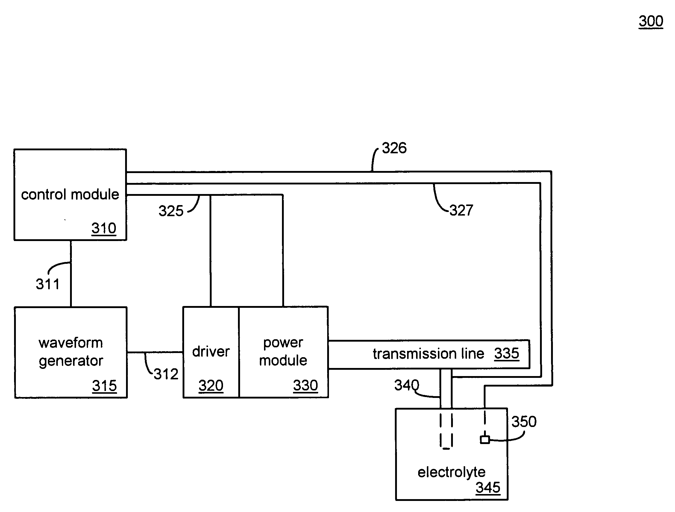
[0083]FIG. 3 shows a block diagram 300 of an embodiment of an electrolytic cell interphase control system. A bus 311 couples a control module 310 to a waveform generator 315. The control module 310 transmits signals to the waveform generator 315 that set the parameters of an output waveform (e.g., duty cycle, amplitude, and period). The bus 311 may also provide feedback to the control module 310 with respect to the output of the waveform generator 315. The output waveform of the waveform generator 315 may include a unipolar signal that has a positive excursion referenced to ground and / or a bipolar signal with positive and negative excursions.

[0084]The waveform generator 315 is coupled to a driver 320 by a signal bus 312. The bus 312 may couple two nodes and carry a single waveform as the output of the waveform generator 315, or it may carry a number of distinct signals between more than two nodes. In a preferred embodiment the driver 320 is driven by an input signal in the range of ...


PUM

PropertyMeasurementUnit
Debye lengthaaaaaaaaaa
temperatureaaaaaaaaaa
relative dielectric constantaaaaaaaaaa

Abstract

An anode and cathode for an electrolytic cell are configured as a low inductance transmission line to enable control of an interphase at an electrode surface. The anode and cathode are coupled to a switched current source by a low inductance path that include a parallel plate transmission line, a coaxial transmission line, or both. The switched current source provides switching between current sources at three or more voltages to provide fast charging and discharging of the double-layer capacitance associated with the electrode surface.

Description

BACKGROUND OF THE INVENTION[0001]1. Field of the Invention[0002]This invention relates to electrolytic cells.[0003]2. Description of Related Art[0004]The boundary between a liquid electrolyte and an electrode typically has an associated region in the electrolyte adjacent to the electrode that separates the electrode from the bulk electrolyte. This region is often referred to as an interphase. As a result of the influence of the electrode surface, the interphase has a composition that is different from the bulk electrolyte. The orientation of molecular dipoles and the concentrations of cationic and anionic species typically differ from the bulk.[0005]Prior Art FIG. 1A shows a representation 100 of an interface between a metal and an electrolyte solution. Such an interface generally becomes electrified, with a net charge developing at the surface of the metal and a near surface region of excess ion concentration developing in the electrolyte solution. In the example of FIG. 1A the exc...

Claims


Application Information

Patent Timeline
Patent Type & Authority Applications(United States)
IPC IPC(8): C25B15/00
CPCC25B15/02C25D17/10C25D21/12C25D5/18
Inventor MATTHEWS, MEHLIN DEAN
Owner MATTHEWS MEHLIN DEAN
Why Eureka
Try Eureka