Method, system and computer program product for efficiently utilizing limited resources in a graphics device

a graphics device and limited resource technology, applied in image data processing, image data processing details, program control, etc., can solve the problems of extreme complexity in applying tuning techniques to maintain reasonable processing requirements for real time environments, limited random access memory (ram) capacity of microcode engines, and insufficient microcode memory space to have monolithic tuned rendering microcode, etc., to achieve the effect of expanding the capabilities of graphics software, saving limited memory, and improving performan

Inactive Publication Date: 2007-11-29
ACTIVISION PUBLISHING
View PDF5 Cites 23 Cited by
  • Summary
  • Abstract
  • Description
  • Claims
  • Application Information

AI Technical Summary

Benefits of technology

[0008] A microcode management system improves the performance and expands the capabilities of graphics software to use more tuning techniques and conserve limited memory on any type of computer platform. Rendering code for a microcode processor is assembled in one or more phases. Well-tuned versions of each phase are stored as distinct modules into a phase code depository for quick and easy access.

Problems solved by technology

However, microcode engines tend to have limited random access memory (RAM) capacity.
In general, there is not enough microcode memory space to have monolithic tuned rendering microcode for each mode that an application may want to use.
Microcode branch instructions can be used to allow a single monolithic rendering code to work in several modes, but at the expense of extreme complexity in applying tuning techniques to maintain reasonable processing requirements for real time environments.
Otherwise, new video games, for example, either would not be able to use the microcode developed for the existing platform, or would not take full advantage of the microcode capabilities.

Method used


Image

  • Method, system and computer program product for efficiently utilizing limited resources in a graphics device
  • Method, system and computer program product for efficiently utilizing limited resources in a graphics device
  • Method, system and computer program product for efficiently utilizing limited resources in a graphics device

Examples


Embodiment Construction

Table of Contents

I. Overview of Microcode Management System

II. Microcode Management

III. Phase Module Sequencing

IV. Phase Module Attributes

V. System Operation

VI. Software and Hardware Embodiments

VII. Conclusion

I. Overview of Microcode Management System

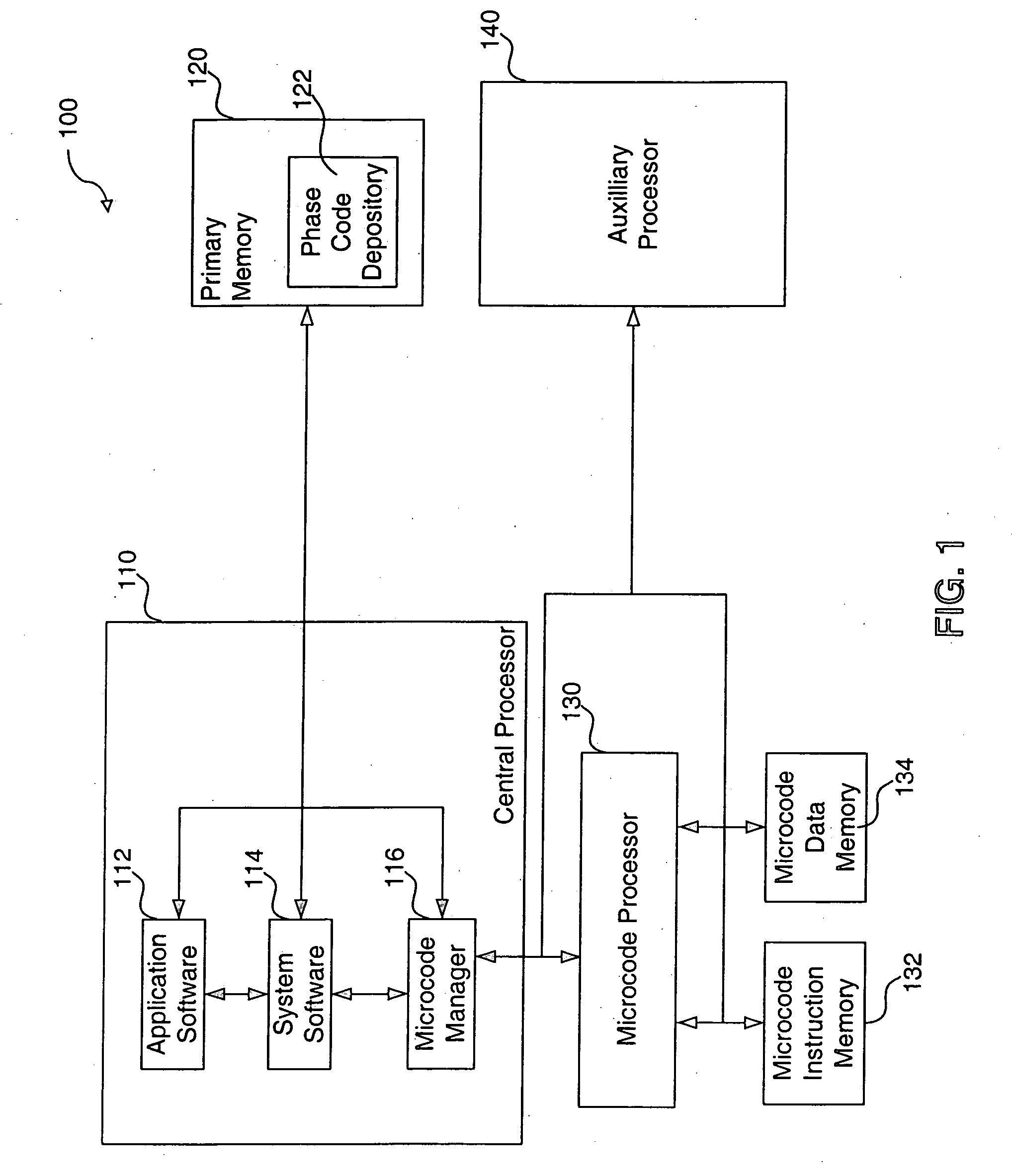
[0023]FIG. 1 illustrates, according to an embodiment of the present invention, a block diagram of a microcode management system 100. As shown, microcode management system 100 includes a central processor 110, primary memory 120, microcode processor 130, microcode instruction memory 132, microcode data memory 134, and auxiliary processor 140. Central processor 110, microcode processor 130, and auxiliary processor 140 represent any commonly known or future-developed computer processor. Central processor 110 can be any processor developed by Intel Corporation, Advanced Micro Devices, Inc. (AMD), API NetWorks (Alpha), ARM Ltd., MIPS Technologies, Inc, or the like. In an embodiment, central processor 110 is the Emotion engin...


PUM


Abstract

A memory management system provides microcode instructions that are divided into multiple tuned phases and stored as separate modules inside a phase code depository. A microcode manager, containing a mode detector, sequence identifier, code loader, drawing data processor and phase executor, interacts with a microcode processor and the phase code depository. The mode detector evaluates a user request for a desired mode. In response to a command from the mode detector, the sequence identifier selects a correct phase sequence that is needed to implement the desired mode. The code loader transfers the phase sequence from the phase code depository to the microcode processor where it is stored in a microcode instruction memory. The memory address for each module within the phase sequence is written to a microcode data memory. The drawing data for the graphics mode is sent from the drawing data processor to the microcode processor, and the phase executor instructs the microcode processor to execute the phase sequence to render the desired mode by processing the drawing data. The resulting data is forwarded to another processor for additional microcode processing, vector processing, rasterization, or the like. The ability to select interchangeable phase modules to implement a desired mode reduces microcode memory requirements and allows easy integration and reuse of previously developed features among different games and other graphics software developers without having to rely on the type of platform.

Description

BACKGROUND OF THE INVENTION [0001] 1. Field of the Invention [0002] The present invention relates generally to memory management, and more particularly to improving the performance of microcoded functionality. [0003] 2. Related Art [0004] Conventional applications for computer graphics use a microcode engine to prepare the instructions to render various graphics modes. To increase the processing speed, the microcode instructions (i.e., microinstructions) include loop routines that are used to execute the rendering instructions. The loop routines are unrolled to reschedule or tune the microinstructions. A direct correlation can be observed between the complexity of graphics programs and the number of required routines. In short as graphics programs become more advanced and sophisticated, a substantial number of lines of microinstructions are needed to render various graphic modes. However, microcode engines tend to have limited random access memory (RAM) capacity. Once RAM is consume...

Claims


Application Information

Patent Timeline
Patent Type & Authority Applications(United States)
IPC IPC(8): G06T1/20G06F9/38
CPCG06F9/223G06F9/3879
Inventor NASH, REUEL WILLIAMYOUNG, MARK ALLANLABARRE, CHARLES
Owner ACTIVISION PUBLISHING
Why Eureka
Try Eureka