Method of Establishing a Communication Link in a Digital Communication System

a communication link and digital communication technology, applied in the field of communication systems, can solve the problems of long delays, relative long delays, and jeopardizing the quality of conversation, and achieve the effect of ensuring the highest possible level of quality of call and conversation and reducing the value of delay

Inactive Publication Date: 2007-11-29
MOTOROLA INC
View PDF5 Cites 4 Cited by
  • Summary
  • Abstract
  • Description
  • Claims
  • Application Information

AI Technical Summary

Benefits of technology

[0012] The present invention beneficially allows for consistent performance of calls with end-to-end encryption regardless of link delay. As the delay is measured during the call a delay used for adjusting the communication system is dynamically changed and this guarantees that the delay value is optimized and the quality of call and conversation is maintained on highest possible level. Further, in duplex calls with excessively long delay the users are notified about the long delay so that special conversation discipline can be applied from the beginning of the call.

Problems solved by technology

In digital communication systems where the voice coding is done using slow bit-rate vocoders and where a part of the communication path is via an air interface, relatively long delays may be incurred.
These long delays are caused by e.g. Forward Error Correction schemes, TDM multiplexing delays, and serialisation delays for low speed links.
If longer delays are added due to other factors such as re-routing over long-delay links, which may be SATCOM links or dial-up links, then the end user may suddenly experience long delays that can jeopardise the conversation quality or make the users to believe that the call is about to be dropped.
In turn the first voice frames will be dumped 116 and this causes a problem for group calls and in particular for end-to-end encrypted calls.
The end-to-end encrypted calls will also suffer because the initial encryption synchronisation is lost and that will add another one or two seconds of audio loss.
However if the receiving party misses this vector (the receiving radio could be switch off) then it would never be able to decrypt the remaining part of the message.
Prior art solutions provide no special means to cope with situations where one party of the call operates on a long delay link and the other party on a short delay link.
Long voice delay due to e.g. a satellite link will, however, cause problems in conversation, as the total one way delay may be 600 ms.
In that situation the efficiency of duplex communication is lost for the first part of the call.

Method used


Image

  • Method of Establishing a Communication Link in a Digital Communication System
  • Method of Establishing a Communication Link in a Digital Communication System
  • Method of Establishing a Communication Link in a Digital Communication System

Examples


Embodiment Construction

[0017] The term “multicast group” herein below refers to a group of Internet Protocol end-points operating in a point to multipoint fashion.

[0018] The term “multicast tree” herein below refers to a structure comprising a number of nodes tied together with a common knowledge of each other forming a network. The structure is a tree structure where the Rendezvous Point is the root. Special IP packets known as multicast packets are floating through this tree in a point to multipoint fashion.

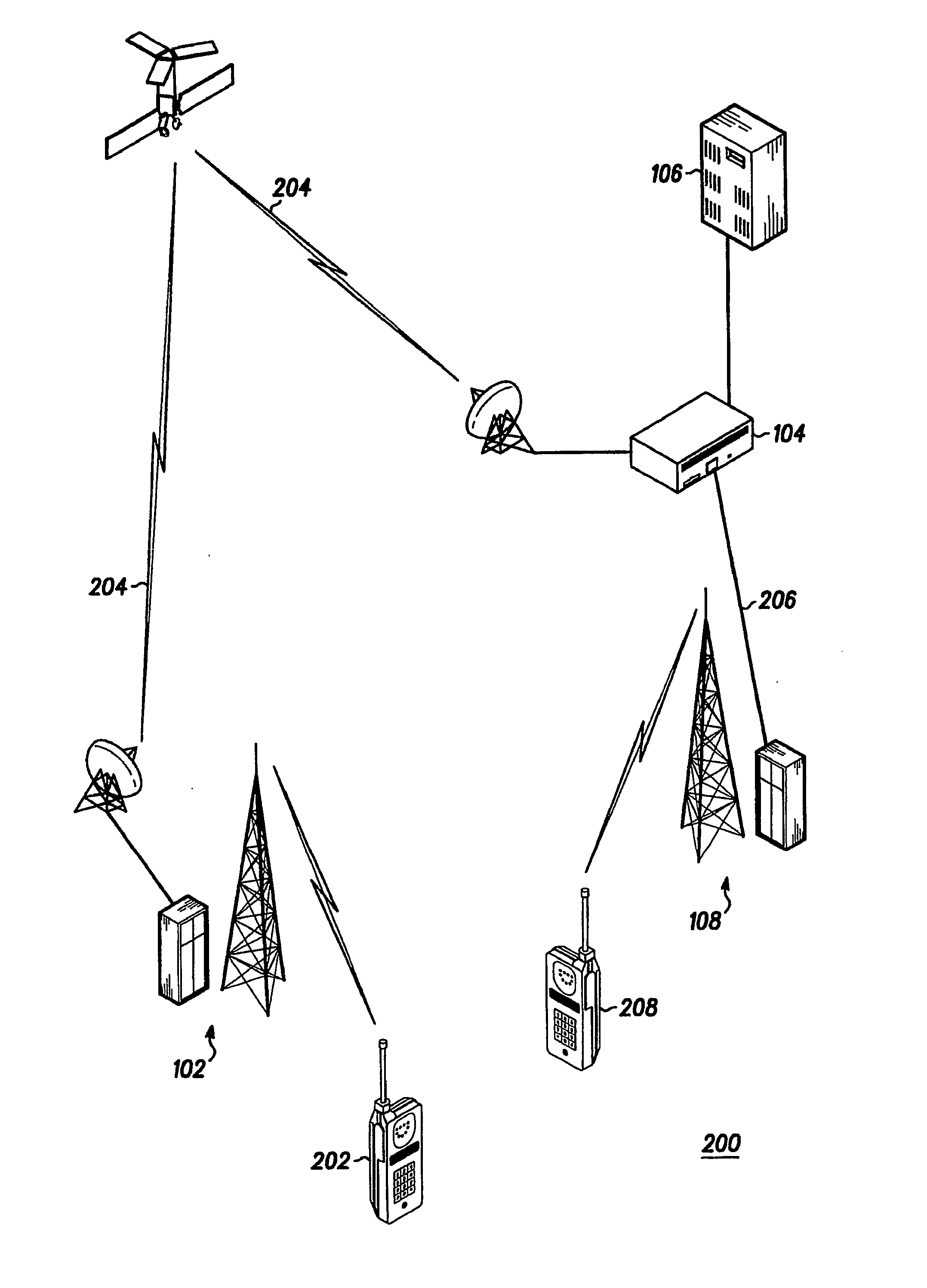
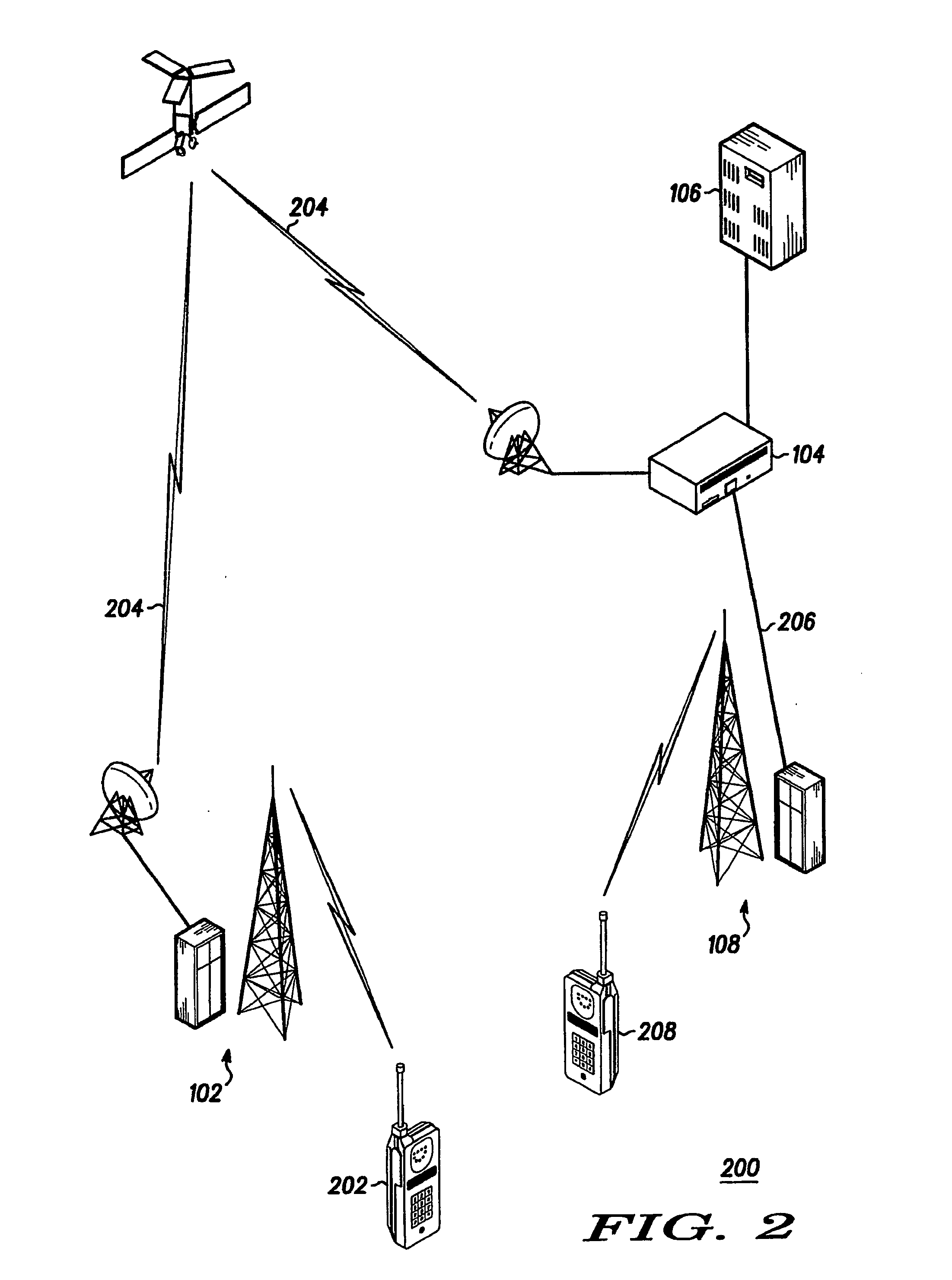
[0019] Referring to FIG. 2 and FIG. 3 one embodiment of a method of establishing communication in a digital wireless communication system 200 according to the present invention is shown. When two communication units 202 and 208 are trying to establish a communication link, wherein a first communication unit 202 operates on a long delay link 204 and a second communication unit 208 operates on a short delay link 206, then to avoid a risk of losing first audio data packets, transmission 118 of audio d...


PUM


Abstract

A method of establishing a communication between at least two communication units in a digital communication system, wherein a first communication unit operates on a long delay link and a second communication unit operates on a short delay link, wherein transmission of audio data blocks is delayed on the short delay link's site.

Description

FIELD OF THE INVENTION [0001] The present invention relates to communication systems, in general, and in particular, to a method of establishing a communication between communication units in a digital communication system. BACKGROUND OF THE INVENTION [0002] In digital communication systems where the voice coding is done using slow bit-rate vocoders and where a part of the communication path is via an air interface, relatively long delays may be incurred. These long delays are caused by e.g. Forward Error Correction schemes, TDM multiplexing delays, and serialisation delays for low speed links. If longer delays are added due to other factors such as re-routing over long-delay links, which may be SATCOM links or dial-up links, then the end user may suddenly experience long delays that can jeopardise the conversation quality or make the users to believe that the call is about to be dropped. [0003] Current solutions anticipates that all links in the system operates with equal delays an...

Claims


Application Information

Patent Timeline
Patent Type & Authority Applications(United States)
IPC IPC(8): H04B7/185
CPCH04B7/18558
Inventor FRANDSEN, SVEND HENRYCHRISTENSEN, BENNYSVENDSEN, PETER WILLIAM HILDING
Owner MOTOROLA INC
Why Eureka
Try Eureka