Gas Detectomg Element and Gas Detecting Device Suited for Same

Inactive Publication Date: 2007-11-29
RIKEN KEIKI KK
View PDF3 Cites 8 Cited by
  • Summary
  • Abstract
  • Description
  • Claims
  • Application Information

AI Technical Summary

Benefits of technology

[0017] The invention according to claim 1 can prevent a gas and a reaction reagent from flowing into an optical density detection portion through an optical density detection window, and therefore can prevent fluctuations in sensitivity caused by diffusion of the reaction reagent and inhibit corrosion.
[0018] The invention according to claim 2 allows the material constituting the optical density detection window to be selected independently of the container.
[0019] The invention according to claim 3 eliminates the labor of affixing a film constituting the optical density detection window and

Problems solved by technology

Such a constitution not only adds an additional level of complication to the structure of the measuring device, but also leads to problems such as breakage of the carrier during feeding due to degradation of the carrier caused

Method used


Image

  • Gas Detectomg Element and Gas Detecting Device Suited for Same
  • Gas Detectomg Element and Gas Detecting Device Suited for Same
  • Gas Detectomg Element and Gas Detecting Device Suited for Same

Examples


first embodiment

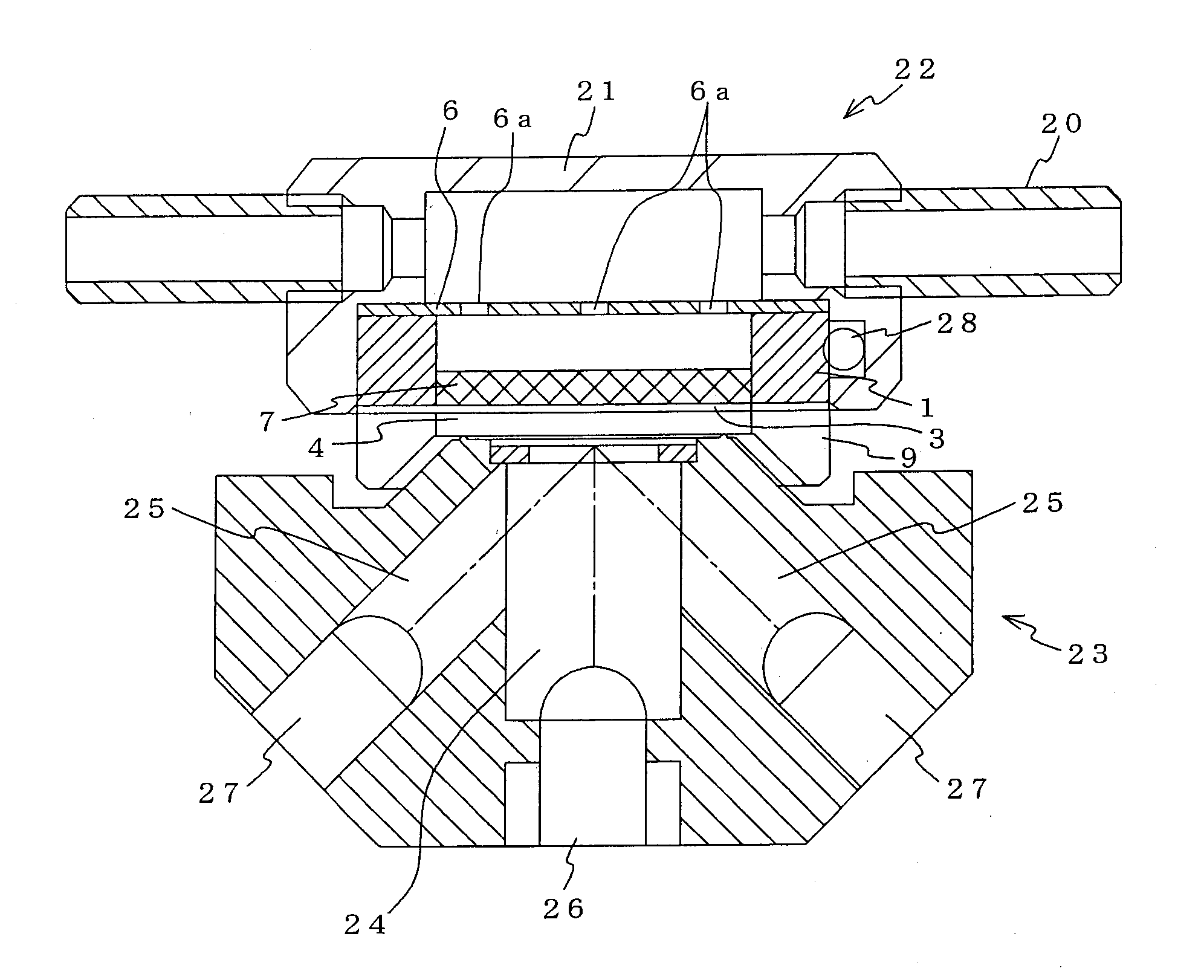
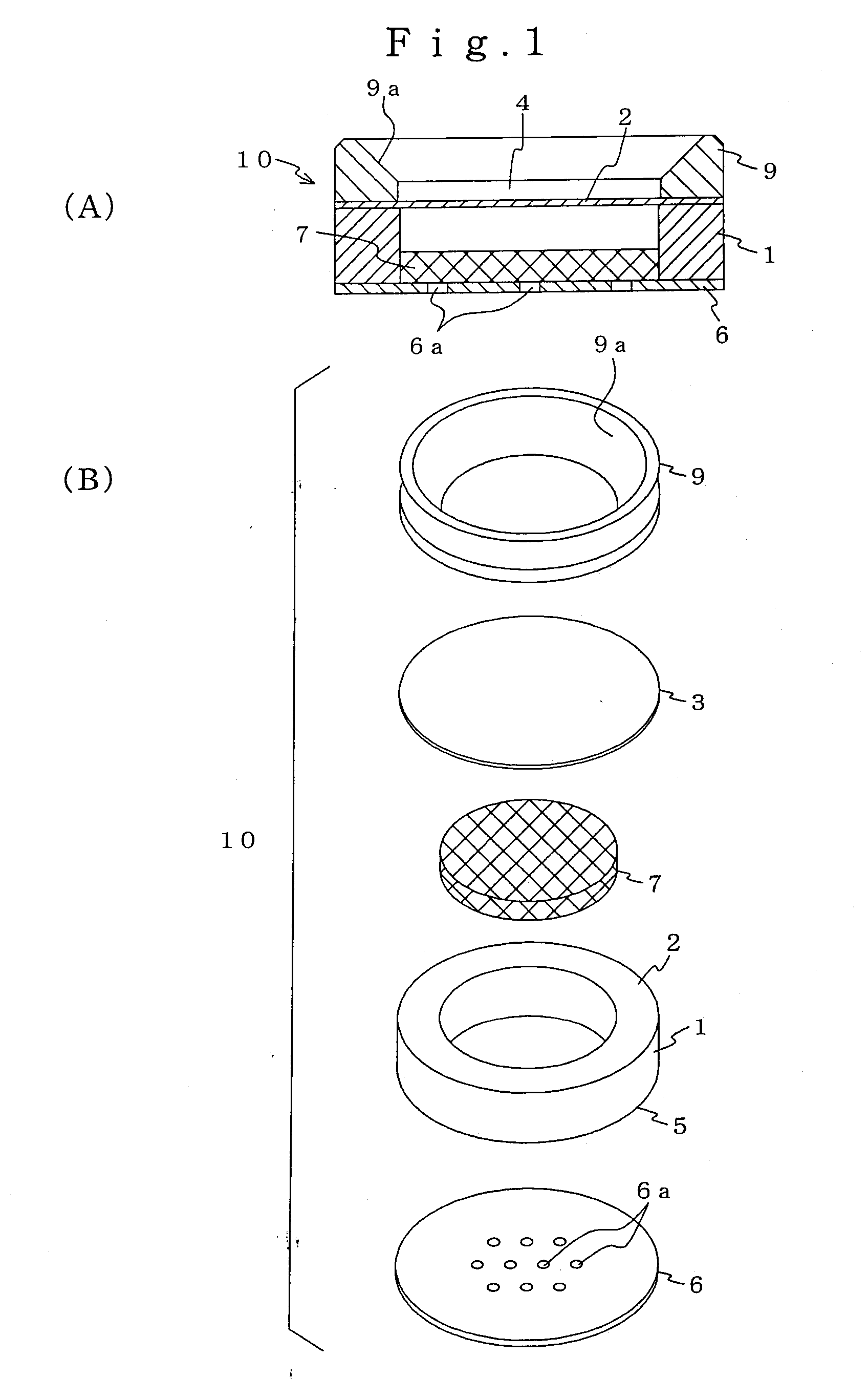
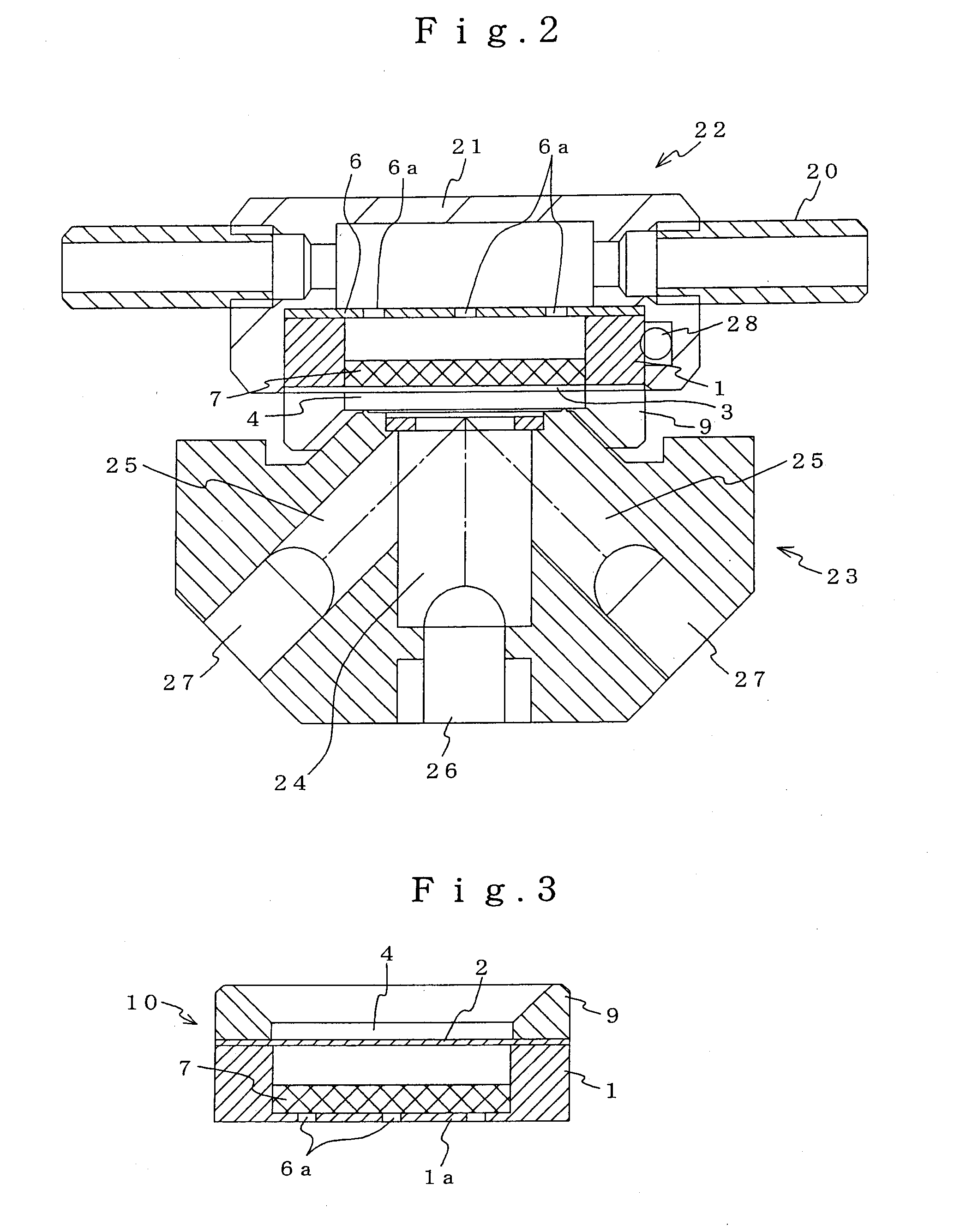
[0028] FIGS. 1(A) and (B) respectively show a cross-sectional view and an exploded perspective view of a gas detecting element of the present invention. A surface 2 on one side of a ring-shaped frame 1 is sealed with a transparent or semi-transparent non-permeable film 3, whereby an optical density detection window 4 is formed. A gas passage layer 6 is formed on another surface 5 on the other side of the frame 1. In a cell formed between the non-permeable film 3 and the gas passage layer 6 is housed a reagent absorbent material 7 that is a porous material of a color density, preferably white, that enables detection of coloration change due to reaction of a reagent. In the present embodiment, the reagent absorbent material 7 is a nonwoven fabric such as glass fiber.

[0029] The gas passage layer 6 is constituted of a material provided with corrosive resistance and light reflectivity, with gas passage holes 6a formed therethrough. The material constituting the gas passage layer 6 may be...

second embodiment

[0043] FIGS. 4(A) and (B) shows the gas detecting element, denoted by the reference numeral 10′. In this embodiment, a frame 1′ formed by injection molding of an optically-transparent polymer material, such as polyethylene, and a thin wall 2′ that serves as the optical density detection window are integrally formed. A tapered portion 1b′ is formed as appropriate on the inner circumferential face of the end portion of the frame 1′.

[0044] In the present embodiment, the gas detecting element 10′ is constituted with the reagent absorbent material 7 loaded from an opening 1a′ side of the frame 1′, with the gas passage layer 6 affixed to the opening 1a′. Similarly to the first embodiment, the reagent absorbent material 7 may be impregnated with the reagent in advance, or impregnated with the reagent after being housed.

[0045] The present embodiment does not require the transparent or semi-transparent non-permeable film 3 as disclosed in the first embodiment, and so eliminates the labor of...


PUM


Abstract

A gas detecting element that can effectively prevent fluctuations in measurement sensitivity caused by diffusion of a reagent as well as the occurrence of corrosion. The gas detecting element comprises a frame 1 with an optical density detection window 4 that is not gas-permeable formed on one side to allow optical density detection, and a gas-permeable window 6 formed on the opposing side, with a reagent absorbent material 7 being housed between the two windows and impregnated with a reagent that undergoes coloration change by reaction with a gas to be measured.

Description

BACKGROUND OF THE INVENTION [0001] 1. Field of the Invention [0002] The present invention relates to a gas detecting element that detects the concentration of a gas by coloration reaction, and a gas detecting device suited to the detecting element. [0003] 2. Description of Related Art [0004] A typical gas detecting element that generates a reaction coloration when gas reacts with a carrier such as cellulose can reliably detect extremely low gas concentrations by extending the sampling time. However, since the carrier is normally formed in a tape shape that is housed on a reel, a paper-feeding mechanism is required. Such a constitution not only adds an additional level of complication to the structure of the measuring device, but also leads to problems such as breakage of the carrier during feeding due to degradation of the carrier caused by the reaction reagent being supported. [0005] In order to solve the aforementioned problems, a gas detecting element has been proposed as disclos...

Claims


Application Information

Patent Timeline
IPC IPC(8): G01N21/00G01N21/78G01N31/22
CPCG01N31/22G01N21/783
Inventor NAKANO, NOBUO
Owner RIKEN KEIKI KK
Why Eureka
Try Eureka