
Shade cutter

a cutting edge and shade technology, applied in the field of cutting edge shades, can solve the problems of safety problems, the opening of the shade cutter is typically too small, and the prior art cutting edge is not suitable for use, and achieves the effect of avoiding the risk of finger injury

Inactive Publication Date: 2007-12-06
HILGENDORF DENNIS J +2
View PDF20 Cites 23 Cited by
  • Summary
  • Abstract
  • Description
  • Claims
  • Application Information

AI Technical Summary

Benefits of technology

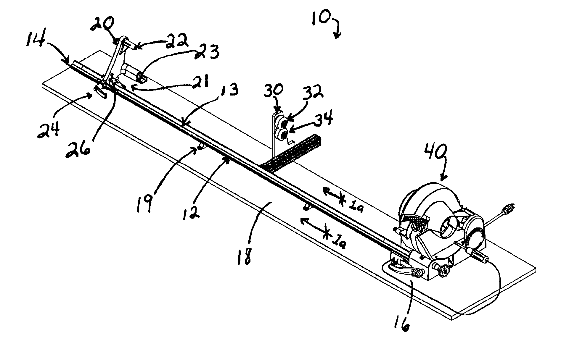
[0008] Further illustrated in FIG. 1 is a shade support bracket 20 slidably affixed to the rail 12 by means of glides 21, which slidably interact with the V-shaped conformation of the rail 12. The shade support bracket 20 comprises a universal inner bearing brace 22 that mates with the shade 200 having both the pin-type and tab-type shade roller ends, therefore minimizing vibrations that were seen in previous designs. The shade support bracket 20 further includes a shade support tightening handle 24 to allow flexibility in the placement of the bracket 20 along the rail 12. A spring loaded pin plunger 26 allows the shade pin 203 (FIG. 9) to be reinserted without having to move the shade support bracket 20.
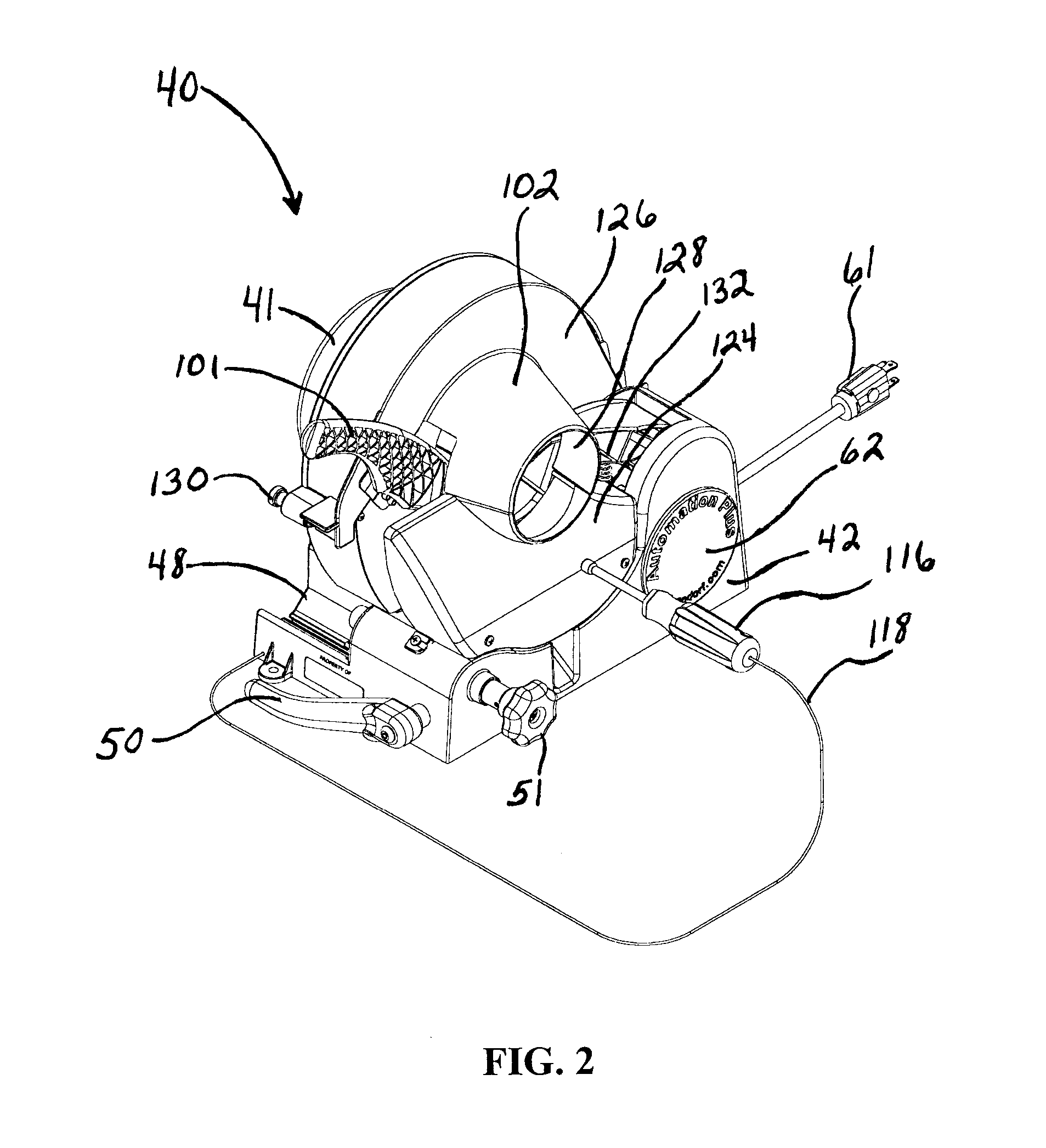
[0014] The machine 40 further comprises a cutting blade 100 supported by a cutting blade handle 101, comprising a stationary steel blade wherein the blade is a single bevel blade. The cutting blade 100 can be rotated at intervals using the spring clip 110 to always have a sharpened portion of the blade 100. The cutting blade 100 includes a circular row of eight rectangular blade notches 109 spaced out over half the blade 100. These notches 109 are used in conjunction with a spring steel clip 110 to prevent blade 100 rotation during cutting and allow for quick and easy blade indexing. The spring steel clip 110 attaches directly between the cutting blade handle 101 and the blade 100 using a bolt 112 (illustrated in FIG. 8). The clip 110 penetrates the blade notch 109 in the blade 100. One side of the clip 110 is perpendicular to the blade notch 109, allowing the blade 100 to stay in a fixed position while cutting the shade 200. The other side of the clip 110 has been designed with a taper (not illustrated). This allows the operator, using a supplied tool 116 attached to the machine 40 by a flexible tether 118 (FIG. 2), to advance the blade 100 rotationally to the next slotted position. This exposes a new sharp cutting surface area of the circular blade 100. The blade notches 109 only cover half of the blade 100 because the other half of the blade 100 is used for cutting of the slats 202, and may be dull from that operation. Once the user reaches the end of the blade notches 109, it is time to replace the blade 100.
[0016] The machine 40 further comprises a protective cutting blade guard 102, preferably made of clear plastic, which includes a spring and safety switch (not illustrated) hidden in shade cutting machine base 42 to protect the user, a stationary cutting blade base 124 affixed to the shade cutting machine base 42, and a rotating cutting blade safety cover 126. Preferably the guard 102 is clear plastic to allow the user to witness the slat cutting operation, a protective measure. The guard 102 further includes a tapered cone 128 that, when closed, forms an enclosed circle to protect the user from the cutting blade 100. The guard 102 is used in conjunction with a shut down mechanism comprising a plunger 130 that, when closed, activates a switch (not illustrated) hidden inside the shade cutting machine base 42 of the machine 40. To operate, the user must pull the plunger 130 out with one hand while lowering the safety cover 126 of the guard 102 with the other hand. If the plunger 130 is not pulled out, the safety cover 126 can not be fully depressed and the machine 40 will not be activated. A switch (not illustrated) is enclosed within the machine 40 to prevent accidental activation or intentional bypass of the safety cover 126. A spring (not illustrated) from the shade cutting machine base 42 to the safety cover 126 is designed to allow the operator to lower the safety cover 126 onto the shade cutting machine base. This ensures immediate machine shutdown if the safety cover 126 is released for any reason.
[0018] The shade cutter of the present invention overcomes many prior art problems. Of greatest importance, the present invention includes several safety features. Specific advantages of the present invention include that fact that the slat cutter is covered. Therefore, there is no risk of injury to fingers. Further, the opening is larger to accommodate larger diameter shades. Further still, there is only one blade, not two, for cutting both the slat and the shade. The pin puller handle operates at a 180-degree motion, which is an advantage over prior art models which requires nearly a full circular motion. The prior art models must be placed at the edge of a table or bench, which creates safety hazards.

Problems solved by technology

There are some issues with the prior art shade cutters though.
For example, the shade cutter opening is typically too small.
Further, the prior art machines have a guillotine type cutting blade to cut the slat, which is a safety problem.
Further still, the shade pieces, i.e., the cast offs, which are coming off of the machine after the shade has been cut, can fly off in a variety of directions and create a safety problem.
In addition, the cutting blade is readily accessible to the operator, creating a safety problem during the cutting operation.

Method used


Image

  • Shade cutter
  • Shade cutter
  • Shade cutter

Examples


Embodiment Construction

[0032] Reference is now made to the figures for the following detailed description of the invention as described in the Summary.

[0033] As previously noted, and referring to FIG. 1, the shade cutter assembly device 10 comprises a shade support measuring rail 12 having a first end 14 and a second end 16. The shade cutter assembly device 10 is generally supported on a base 18 by supports 19.

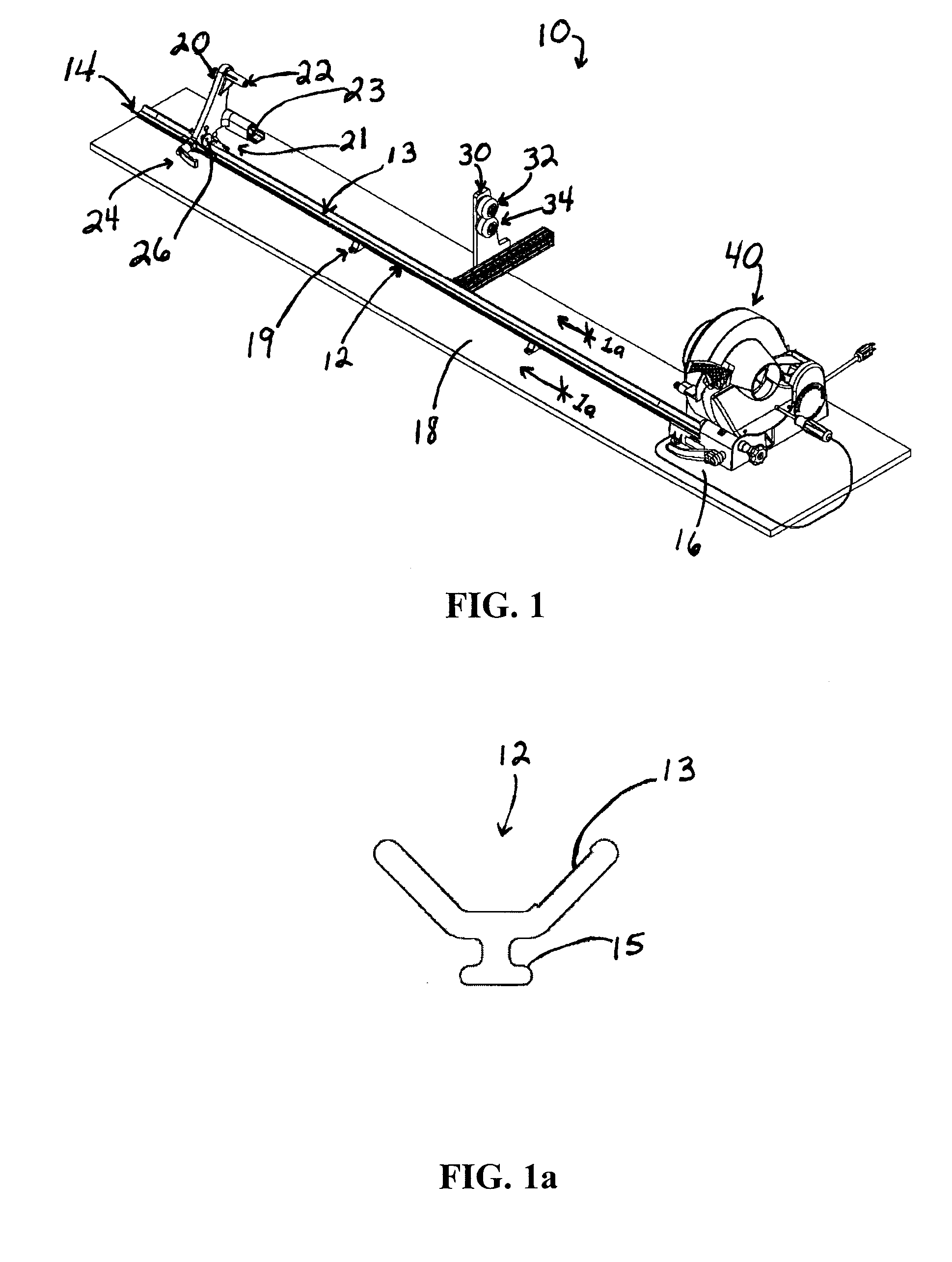
[0034] Referring now to FIG. 1a, the rail 12 is configured in a V shape with a T-shaped base 15 on its dorsal side for positioning the rail 12 on the base 18 by means of shade support brackets 19. The base 18 can be made of any of a number of materials, including wood, plywood, plastic, metal or other types of extruded board material. It is also within the scope of the present invention to position the shade cutter assembly device 10 directly on an existing bench or table.

[0035] As illustrated in FIG. 1a, a shallow slot 13 extends the length of the rail 12. The slot is ideally suited for the opti...


PUM

PropertyMeasurementUnit
Lengthaaaaaaaaaa

Abstract

A shade cutter for trimming rotating window shades includes a larger opening to accommodate larger diameter shades, one blade for cutting both the slat and the shade, a mechanism to remove the shade pin, a protective cover for the blade, and a motor contained in the shade cutting machine base.

Description

REFERENCE TO RELATED APPLICATION [0001] The application claims priority to U.S. Provisional Application entitled “Shade Cutter,” Ser. No. 60 / 808,741, filed May 26, 2006, which is incorporated herein by reference in its entirety.FIELD OF THE INVENTION [0002] The present invention is directed to a machine for trimming rotating window shades. DESCRIPTION OF THE PRIOR ART [0003] Shade cutters have been around for many years. The primary purpose of a shade cutter is to cut a window shade to a precise dimension. In this manner, a standard length window shade can be formed in the factory and then sent to the customer or customer's shop for measurement and trimming if necessary. [0004] There are some issues with the prior art shade cutters though. For example, the shade cutter opening is typically too small. Newer shades are made with different materials and / or insulated which increases the diameter and makes the older shade cutter models inoperable. Further, the prior art machines have a g...

Claims


Application Information

Patent Timeline
IPC IPC(8): B26D1/00
CPCB26D3/16B23D45/124Y10T83/04Y10T83/929
Inventor HILGENDORF, DENNIS J.HILGENDORF, DAVID A.RYNES, DAVID A.
Owner HILGENDORF DENNIS J
Learn More