Protective cover structure for rammer

a protection cover and rammer technology, applied in the direction of machines/engines, combustion air/fuel air treatment, roads, etc., can solve the problems of disabling the machine, unstable posture, and easy falling of the machine, and achieve the effects of preventing damage, small weight, and high strength

Inactive Publication Date: 2007-12-06
MIKASA SANGYO KK
View PDF7 Cites 9 Cited by
  • Summary
  • Abstract
  • Description
  • Claims
  • Application Information

AI Technical Summary

Benefits of technology

[0014]The protective cover structure in accordance with the present invention comprises below a rear surface of the crank chamber a protective stand that has a function of protecting a lower-half section of the power engine and comprises in a protruding condition thereof support frames for supporting from below the guard covers disposed on both sides of the crank chamber and power engine along both sides. Therefore, when the rammer tumbles to the right or to the left, the impact is absorbed by the support frame and the rear section of the guard cover, and the power engine can be prevented from damage.
[0015]The guard cover is formed from a synthetic resin, has a small weight, and can be molded to any shape. A high strength is attained even when the guard cover has a large shape such that can cover not only the side surface of the power engine, but also both sides of the crank chamber and power engine. Furthermore, an effective shape can be obtained that enables a free selection of optimum conditions for the guard cover such as the position of a ventilation hole through which the exhaust gas obtained after the power engine has been cooled has to be discharged and a shape that has to be provided to a protruding components such as a muffler.
[0016]Furthermore, the guard cover made from a synthetic resin has a small w

Problems solved by technology

Therefore, in a stationary state when the compaction plate is supported by the ground, the center of gravity of the machine is positioned in the upper part of the machine body, the posture is unstable, and the machine can easily tumble.
The resultant problem is that if the machine is easy to tumble, it can tumble in which case the power engine positioned in the upper section of the machine and important components associated therewith will hit the ground and be damaged, thereby disabling the machine.
However, the following problem is associated with the structure in which the power engine is guarded from the outside with a metallic cover plate.
The cover plate serves to prevent the power engine components from damage when the machine tumbles, but when the cover plate is made from a thin metal sheet, the strength of the cover is insufficient to withstand the impact when the machine tumbles, the cover is deformed, and the power engine components cannot be prevented from damage.
On the other hand, when a thick metallic cover is used to prevent the cover p

Method used


Image

  • Protective cover structure for rammer
  • Protective cover structure for rammer
  • Protective cover structure for rammer

Examples


embodiments

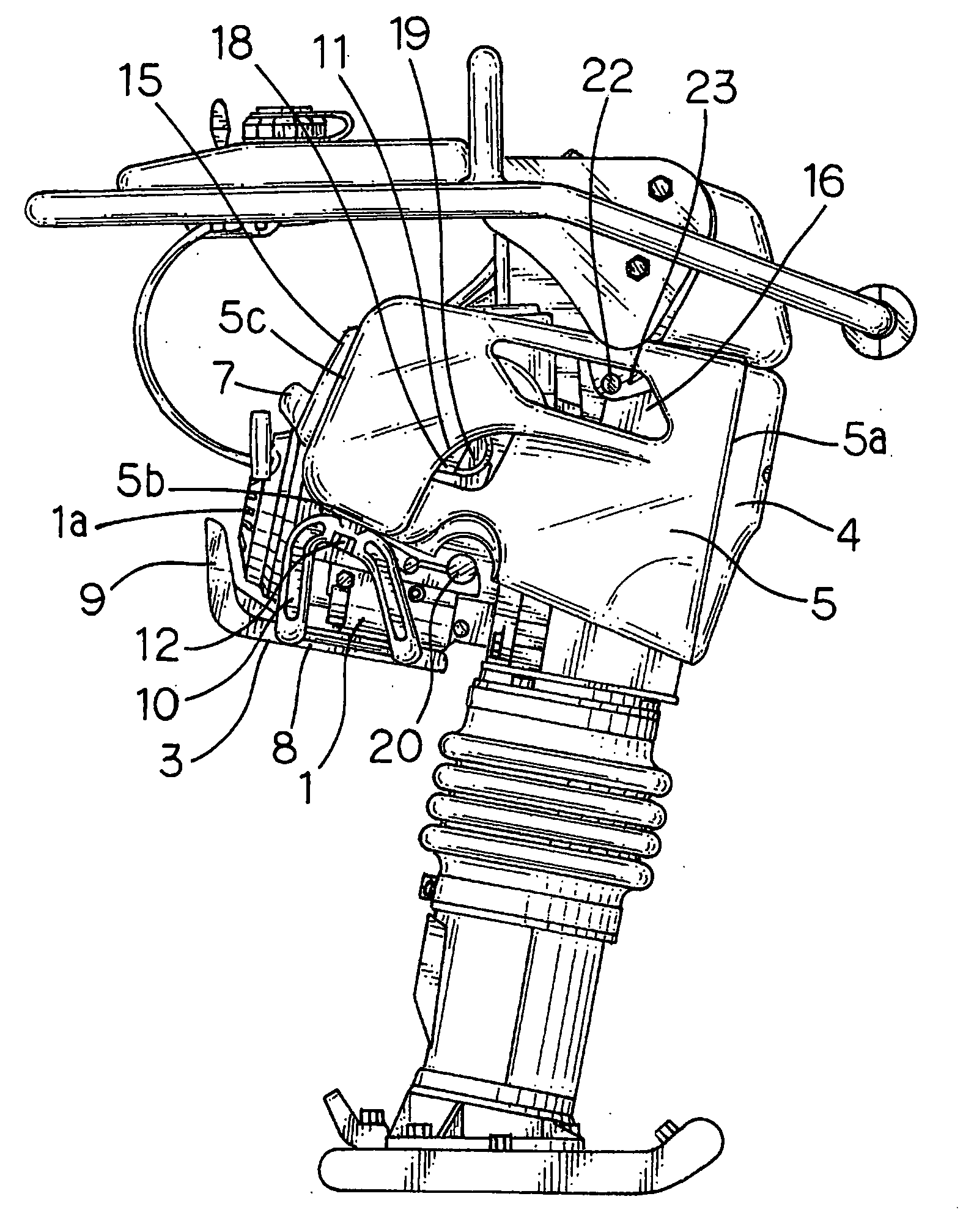
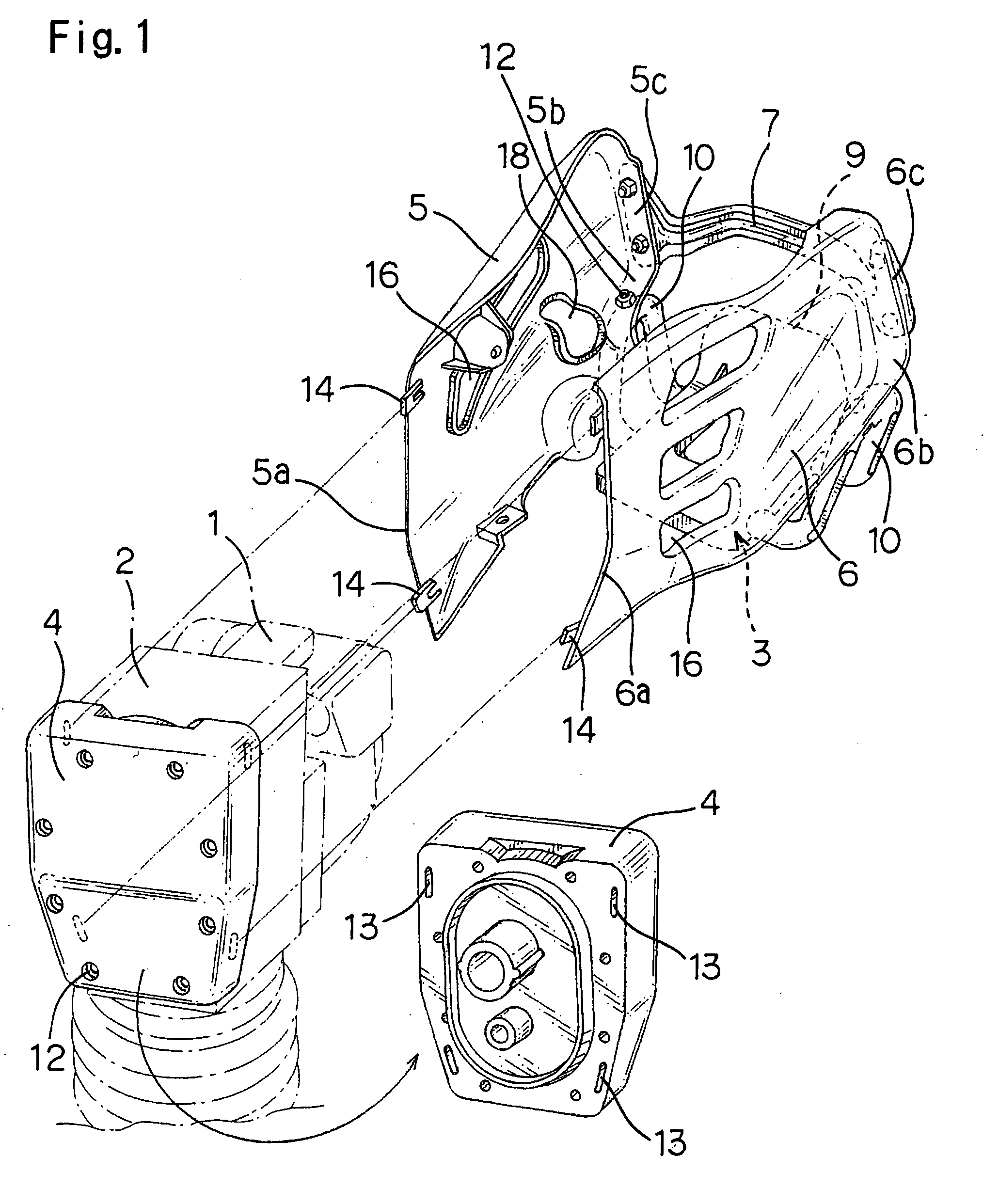
[0026]The protective cover structure for a rammer in accordance with the present invention will be explained below based the embodiment thereof illustrated by FIG. 1. FIG. 1 is a perspective view illustrating the basic configuration of the protective cover structure. This protective cover structure comprises a power engine protective stand 3 attached to the lower surface of a power engine 1 that is connected and fixed to the rear surface of a crank chamber 2, a front plate 4 attached to the front surface of the crank chamber 2, a pair of left and right guard covers 5, 6 disposed on the outer surface on both sides of the crank chamber 2 and power engine 1, and a linking pole 7 for linking integrally the upper portions of the rear sections of both guard covers 5, 6 on the power engine side.

[0027]As shown in FIG. 2 and FIG. 3, the power engine protective stand 3 is molded from a Nylon resin or the like and serves to protect the lower-half section of the power engine 1 when the rammer t...


PUM


Abstract

The present invention provides a protective cover structure for a rammer for which a guard cover plate of a power engine in a rammer is molded from a synthetic resin allowing any shape to be freely obtained and having small weight, high strength, and impact absorption ability. The cover plate is configured so that it can be assembled and disassembled by simple operations, has good endurance with respect to severe vibrations and can reduce the damage of the machine body due to the adequate impact absorption ability even when the rammer tumbles.
Front end sections of guard covers disposed on both sides of a power engine are joined and fixed to the front surface section of the crank chamber, lower sections of the rear portions are supported by support frames of a protective stand provided at the lower surface of the power engine, and the rear sections of the rear portions are linked integrally by a linking transverse pole.

Description

BACKGROUND OF THE INVENTION[0001]1. Field of the Invention[0002]The present invention relates to the improvement of a guard cover for protecting a crank chamber and a power engine of a rammer for compacting a road surface by hitting the road surface with a compaction plate that moves up and down.[0003]2. Description of the Related Art[0004]A rammer has a structure comprising a power engine providing a rotary movement, a leg section extendable below a crank chamber that converts the rotary movement into an up-down movement, and a compaction plate. Therefore, in a stationary state when the compaction plate is supported by the ground, the center of gravity of the machine is positioned in the upper part of the machine body, the posture is unstable, and the machine can easily tumble. The resultant problem is that if the machine is easy to tumble, it can tumble in which case the power engine positioned in the upper section of the machine and important components associated therewith will ...

Claims


Application Information

Patent Timeline
IPC IPC(8): F02B65/00
CPCE02D3/046E01C19/35
Inventor TANAKA, GIICHIHARASHIMA, YOSHINORINAGASAWA, KENICHIMURAMOTO, KENICHI
Owner MIKASA SANGYO KK
Why Eureka
Try Eureka