
Flat heating element

a technology of heating elements and heating elements, applied in the field of flat heating elements, can solve the problems of copper conductors, unsuitable current concentrations, and overheating,

Inactive Publication Date: 2007-12-06
GENTHERM GMBH
View PDF12 Cites 35 Cited by
  • Summary
  • Abstract
  • Description
  • Claims
  • Application Information

AI Technical Summary

Benefits of technology

[0014]To enhance the state of the art, a heating element, a seat and

Problems solved by technology

Precisely because of the networking of the heating conductors among one another, undesired concentrations of current can arise when an electrode breaks.
Thereby overheating may occur in this region.
Conductors made of copper, however, can be stressed mechanically only to a limited extent, so that malfunctions due to material fatigue and / or breakage may occur.
This is due primarily to the copper material's insufficient fatigue strength under reversed bending.
Breakage of contact or heating conductors can occur in such heating elements.
In this case, an interruption of the supply of electrical power occurs at the breakage point.
There are application cases, however, in which the heating elements described there are still not sufficiently robust.
If the applied silver is not free of pores, however, the copper can still be attacked.
Moreover, silver diffuses into the copper over time.
Thereby an Ag—Cu alloy is formed that is very brittle.
Breakages of this boundary layer form the beginnings of cracks, which may also put the conductor at risk.
An important disadvantage of this material combination is the relatively high cost and only limited corrosion resistance of the clad wires.
The copper sheath does conduct the electric current sufficiently well for most applications, but for many purposes it is not sufficiently resistant to corrosion.
The heating conductors described there are relatively thick, however, and therefore not suited to vehicle seats since they interfere with comfortable sitting.
Unfortunately, undesired initiation of this self-destruction effect can occur due to material fatigue, so that such heating elements sometimes have an undesirably short service life.

Method used


Image

  • Flat heating element
  • Flat heating element
  • Flat heating element

Examples


Embodiment Construction

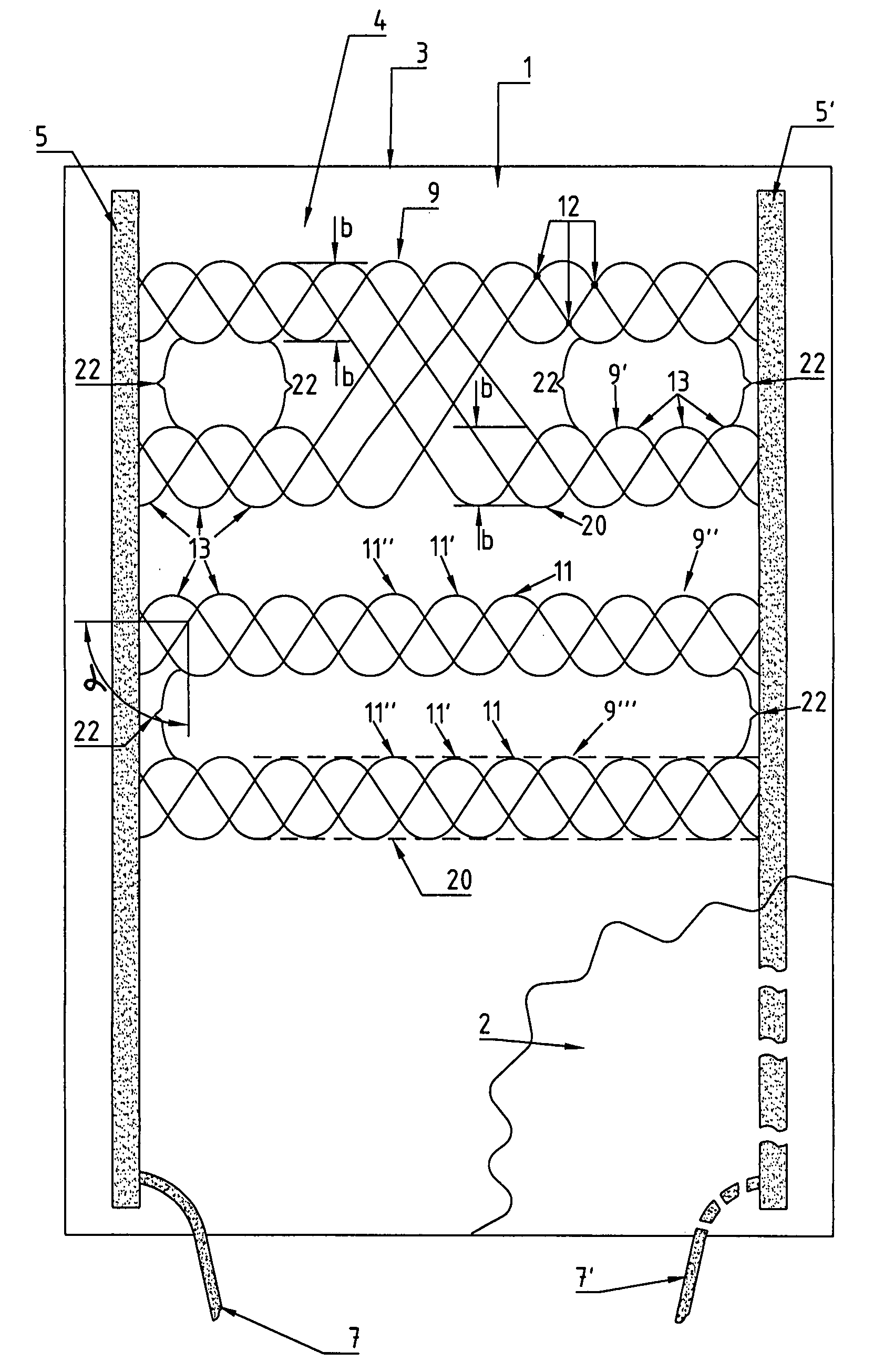
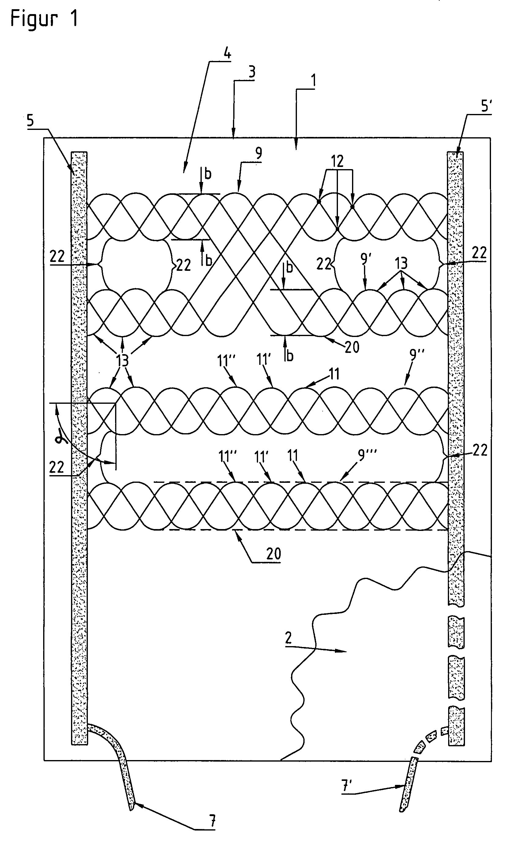
[0034]Figure shows a heating element 1. It comprises a carrier layer 3. Carrier layer 3 is preferably produced from a textile material such as a knit or a felt material. In the present case it has rectangular dimensions. Two electrodes 5, 5′ are arranged along the long edges of carrier layer 3. The electrodes are formed from, for instance, conductive threads, copper stranded wires, electrically conductive adhesives, electrically conductive foils, combinations thereof or the like.

[0035]Electrodes 5, 5′ are arranged at least roughly parallel to one another, and are each connected at one of their ends via power supply line 7, 7′ to a current or voltage source 70 (shown in FIG. 4).

[0036]Bundles 9, 9′, 9″ of heat conductors 11, 11′, 11″ run at an angle (α) to the electrodes. In the present case, these bundles 9, 9′, 9″ are arranged perpendicular to the electrodes. They are arranged on carrier layer 3. They are preferably fixed there with adhesive. They can also be laid on, sewn on or kni...


PUM


Abstract

The present invention relates to a heating element for heating at least one surface contacted at times by a user, with a plurality of heating conductors or heating conductor sections that are directly or indirectly connected electrically to one another, at least in part by mutual contact, with at least one heating conductor or heating conductor section which, upon exceeding a permissible maximum temperature, at least temporarily loses its electrical conductivity at least in part. It is provided that the electrical resistance of at least two heating conductors or heating conductor sections is dependent at least in part on its mechanical strain, that these heating conductors or heating conductor sections are electrically connected to one another in parallel, and that they are separated from one another at least in sections by a spacing zone in order to prevent electrical connection between them in spacing zone.

Description

CLAIM OF BENEFIT OF EARLIER FILING DATE[0001]The present application claims the benefit of the filing date of German Application Nos. DE 102006026047.3 (filed Jun. 1, 2006) the contents of which are hereby incorporated by reference in their entirety.TECHNICAL FIELD[0002]The present invention relates to flat heating elements, particularly for heating user-contacted surfaces in the passenger compartment of a vehicle, to seats, particularly for vehicles, as well as to vehicles according to the preambles of the independent claims.BACKGROUND OF THE INVENTION[0003]A heating element in which a plurality of interconnected heating conductors is laid between two electrodes is known from DE 101 12 405. In case one of the heat conductors breaks, the networking of the heat conductors among one another leads to a diversion of current around the breakage point. Despite its breakage, this heating element 1 will continue to uniformly heat the surface to be heated. Precisely because of the networking...

Claims


Application Information

Patent Timeline
IPC IPC(8): H05B3/02D03D15/533
CPCB60N2/5685H05B3/34H05B3/342H05B2203/003H05B2203/004D07B1/147H05B2203/011H05B2203/017H05B2203/029H05B2203/033H05B2203/005D07B2401/203
Inventor WEISS, MICHAEL
Owner GENTHERM GMBH
Learn More