Induction Heating Cooker

a technology for induction heating and cookers, which is applied in the direction of induction heating, electric/magnetic/electromagnetic heating, induction heating control, etc., can solve the problems of insufficient heating power, poor cooking performance, and high electrical conductivity, so as to reduce the buoyancy effect of the pot and reduce the electrical conductivity. , the effect of high electrical conductivity

Inactive Publication Date: 2007-12-06
PANASONIC CORP
View PDF2 Cites 43 Cited by
  • Summary
  • Abstract
  • Description
  • Claims
  • Application Information

AI Technical Summary

Benefits of technology

[0005] An induction heating cooker in the present invention implements a quick-responding temperature control with an infrared sensor when heating a pot made of a magnetic metal material (iron, cast iron, magnetic stainless steel, etc.) or a metal material lower in electrical conductivity than aluminum, such as a non-magnetic stainless steel. Meanwhile, when heating a non-magnetic pot having a high electrical conductivity that is comparable to or higher than that of aluminum (hereinafter referred to as the high electrical conductivity), the induction heating cooker reduces the buoyancy effecting to the pot by making use of a buoyancy reducing plate, and at the same time lowers the influence of an infrared radiation from the buoyancy reducing plate. Thus it alleviates the insufficiency of cooking power to be caused due to the temperature control by the infrared sensor, and improves the cooking performance. The induction heating cooker in the present invention includes a top plate configured to place a cooking pot thereon, a heating coil disposed underneath the top plate, an inverter circuit, a pot type discriminator, a buoyancy reducing plate made of a non-magnetic-material having the high electrical conductivity, an infrared sensor, a temperature calculator, and a controller. The inverter circuit supplies a high frequency current to the heating coil. The pot type discriminator judges whether the pot is made of a non-magnetic meal material having the high electrical conductivity, or a magnetic metal material or a non-magnetic metal lower in electrical conductivity than aluminum. The buoyancy reducing plate is disposed between the top plate and the heating coil; the plate is configured to alleviate the buoyancy effecting to a pot made of the high electrical conductivity material during induction heating. The infrared sensor detects the infrared radiation from the pot. The temperature calculator calculates a temperature of the pot based on an output from infrared sensor. The controller controls an output from the inverter circuit according to a temperature calculated by the temperature calculator, when the placed pot is judged to be made of a magnetic metal material or a non-magnetic metal lower in electrical conductivity than aluminum. When the pot type discriminator judges that the pot is made of a non-magnetic metal material having the high electrical conductivity, the controller nullifies a temperature detection made by the temperature calculator. Thereby, erroneous temperature detection caused by a self-generated heat at the buoyancy reducing plate reaching incidentally to the infrared sensor is prevented. The insufficiency of heating power due to the temperature control with an infrared sensor can be alleviated. Therefore, it enables a quick-responding cooking with the infrared sensor when heating a pot made of a magnetic material or a non-magnetic metal having a low electrical conductivity; when heating a pot made of a non-magnetic metal having the high electrical conductivity, the erroneous temperature detection due to the infrared radiation from the buoyancy reducing plate can be lowered. The overall cooking performance is thus improved.

Problems solved by technology

However, an induction heating cooker of the above-described structure designed to be compatible with a low resistance cooking pot made of aluminum, copper or the like material having a low magnetic permeability and a high electrical conductivity comparable to or higher than that of aluminum demonstrates a poor cooking performance.
This invites an insufficiency in the heating power, and deteriorates the cooking performance.

Method used


Image

  • Induction Heating Cooker
  • Induction Heating Cooker
  • Induction Heating Cooker

Examples


first exemplary embodiment

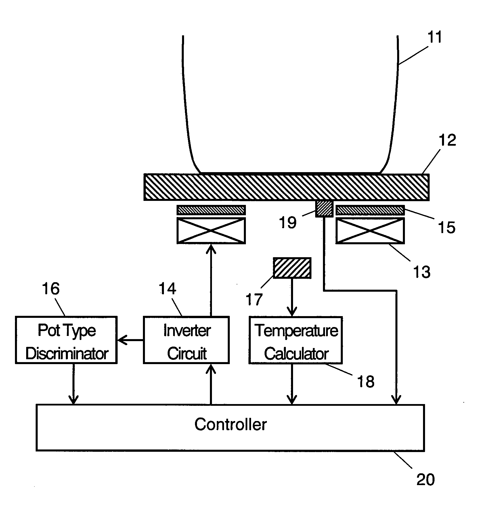
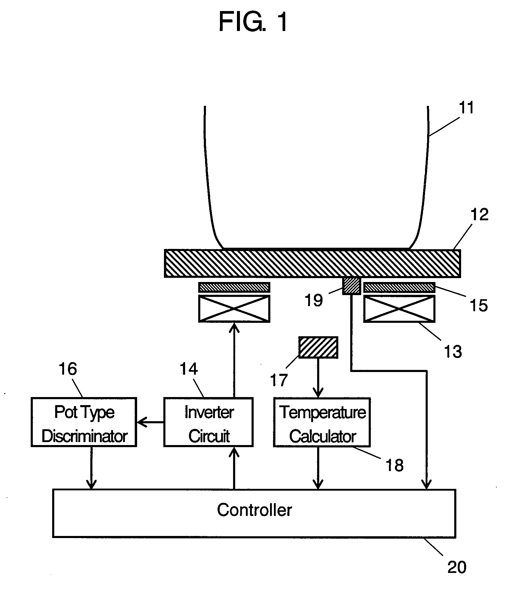
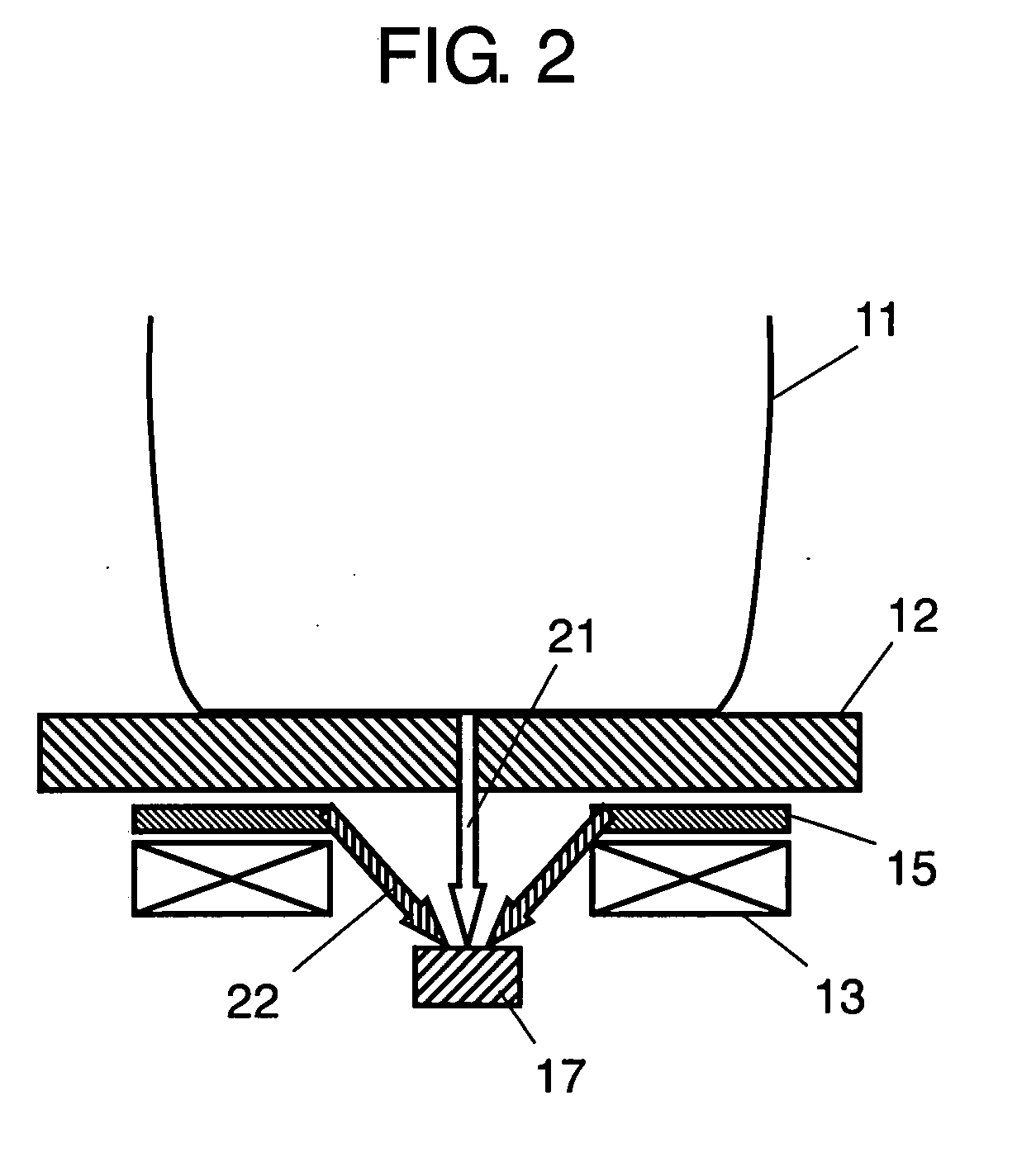
[0033]FIG. 1 is a cross sectional view of an induction heating cooker in accordance with a first embodiment of the present invention, which shows the concept of structure. FIG. 2 is a cross sectional view which shows infrared radiations from pot 11 and buoyancy reducing plate 15. Top plate 12 places pot 11 thereon. Heating coil (hereinafter referred as “coil”) 13 is disposed underneath top plate 12 and heats pot 11 by means of induction heating. Inverter circuit 14 supplies a high frequency current higher than 20 kHz to coil 13. Buoyancy reducing plate 15 is made of aluminum, copper or the like non-magnetic metal having a high electrical conductivity comparable to or higher than that of aluminum, and is disposed between top plate 12 and coil 13. The buoyancy reducing plate alleviates the buoyancy which works to a current induced in pot 11 by magnetic flux generated by coil 13 during an induction-heating of pot 11. Describing practically, buoyancy reducing plate 15 reduces a floating...

second exemplary embodiment

[0045]FIG. 4 is a cross sectional view showing the structural outline of an induction heating cooker in accordance with a second embodiment of the present invention. Those portions identical to those of the first embodiment are designated with the same symbols, and detailed description thereon is eliminated. The point of difference as compared with the first embodiment is that controller 23 is provided in place of controller 20, and time counter 24 and informer 25 is provided additionally.

[0046] Controller 23 configured to control an automatic cooking scheme, controls an output from inverter circuit 14 based on the outputs from discriminator 16, temperature calculator 18 and first temperature sensor 19 in accordance with a certain specific algorithm. Time counter 24 counts the time of heating a pot which is made of a non-magnetic metal material having the high electrical conductivity in a state that the pot is recognized by discriminator 16 to be made of such a material. Informer 2...


PUM

PropertyMeasurementUnit
temperatureaaaaaaaaaa
frequencyaaaaaaaaaa

Abstract

An induction heating cooker has a top plate, a heating coil, an inverter circuit, a pot type discriminator, a non-magnetic-metal buoyancy reducing plate having a high electrical conductivity, an infrared sensor, a temperature calculator, and a controller. The pot type discriminator judges whether a pot is made of a non-magnetic metal material having a high electrical conductivity, or a magnetic metal material or a non-magnetic metal lower in electrical conductivity than aluminum. The temperature calculator calculates the temperature of the pot from an output from the infrared sensor that detects infrared radiation from the pot. The controller controls an output from the inverter circuit according to a calculated temperature by the temperature calculator, and, when the pot is judged to be made of a non-magnetic metal material by the pot type discriminator, nullifies temperature detection made by the temperature calculator.

Description

TECHNICAL FIELD [0001] The present invention relates to an induction heating cooker which includes an infrared sensor for measuring temperature. BACKGROUND ART [0002]FIG. 5 is a cross sectional view of a conventional induction heating cooker showing the concept of its structure. Cooking pot 41 as a load of heating is placed on top plate 42. Heating coil (hereinafter referred to as coil) 43 heats cooking pot 41. Infrared sensor 44 detects infrared radiation of cooking pot 41, and temperature calculator 45 calculates a temperature of cooking pot 41 based on an output from infrared sensor 44. Controller 46 controls current supply to coil 43 in accordance with an output from temperature calculator 45. In the above-configured induction heating cooker, the temperature of cooking pot 41 is detected directly by means of an infrared radiation coming from the bottom of cooking pot 41; thus it can make use of quick-responding temperature detection. The induction heating cooker of the above-des...

Claims


Application Information

Patent Timeline
Patent Type & Authority Applications(United States)
IPC IPC(8): H05B6/06
CPCH05B2213/07H05B6/062
Inventor TOMINAGA, HIROSHIWATANABE, KENJIMAE, CHIKA
Owner PANASONIC CORP
Why Eureka
Try Eureka