Vibration Generating Motor

a vibration generation and motor technology, applied in the field of vibration generation motors, can solve the problems of significant loss of reliability in the power supply connection mechanism, poor vibration condition, insufficient continuity, etc., and achieve the effects of eliminating contact portion wear, high reliability, and long life of the power supply terminal

Inactive Publication Date: 2007-12-06
NAMIKI SEIMITSU HOSEKI KK
View PDF8 Cites 6 Cited by
  • Summary
  • Abstract
  • Description
  • Claims
  • Application Information

AI Technical Summary

Benefits of technology

[0052] As described above, this invention can realize high reliability in a connection between a power supply terminal of a vibration motor and a power supply land of a circuit board of an apparatus main unit on which the power supply terminal is to be mounted, power supply stable in the long term and long life of a power supply terminal thanks to elimination of wear of a contact portion caused by vibration. Thus, this invention provides a vibration motor that is electrically operated in the more stable condition and has higher durability than a conventional vibration motor. Furthermore, this invention provides a vibration motor having a structure for connecting a power supply terminal without allowing the circuit board and the power supply land to be subjected to excessive stress or load and simultaneously having a structure for holding the vibration motor in order to surely transmit generated vibration to the housing of the apparatus main unit.
[0053] That is to say, this invention provides-a vibration motor comprising a vibration generating mechanism having a rotating shaft attached with a weight, a housing case for accommodating at least a part of the aforementioned vibration generating mechanism, and a pair of power supply terminals protruding from the aforementioned housing case that are connected to a power supply land of a circuit board of power source side to be mounted in a housing of a portable apparatus in the elastically contacting condition to supply power to the aforementioned vibration generating mechanism, wherein a bending point and an action point of a movable portion of power supply terminal that is movable in the direction in whi

Problems solved by technology

Thus, contact wear due to vibration frequently found at the area in contact with a power supply land surface results in an insufficient continuity problem.
The aforementioned contact wear due to vibration can be a cause of generating black powder due to sparks at the electrical contact, leading to an important

Method used


Image

  • Vibration Generating Motor
  • Vibration Generating Motor
  • Vibration Generating Motor

Examples


first embodiment

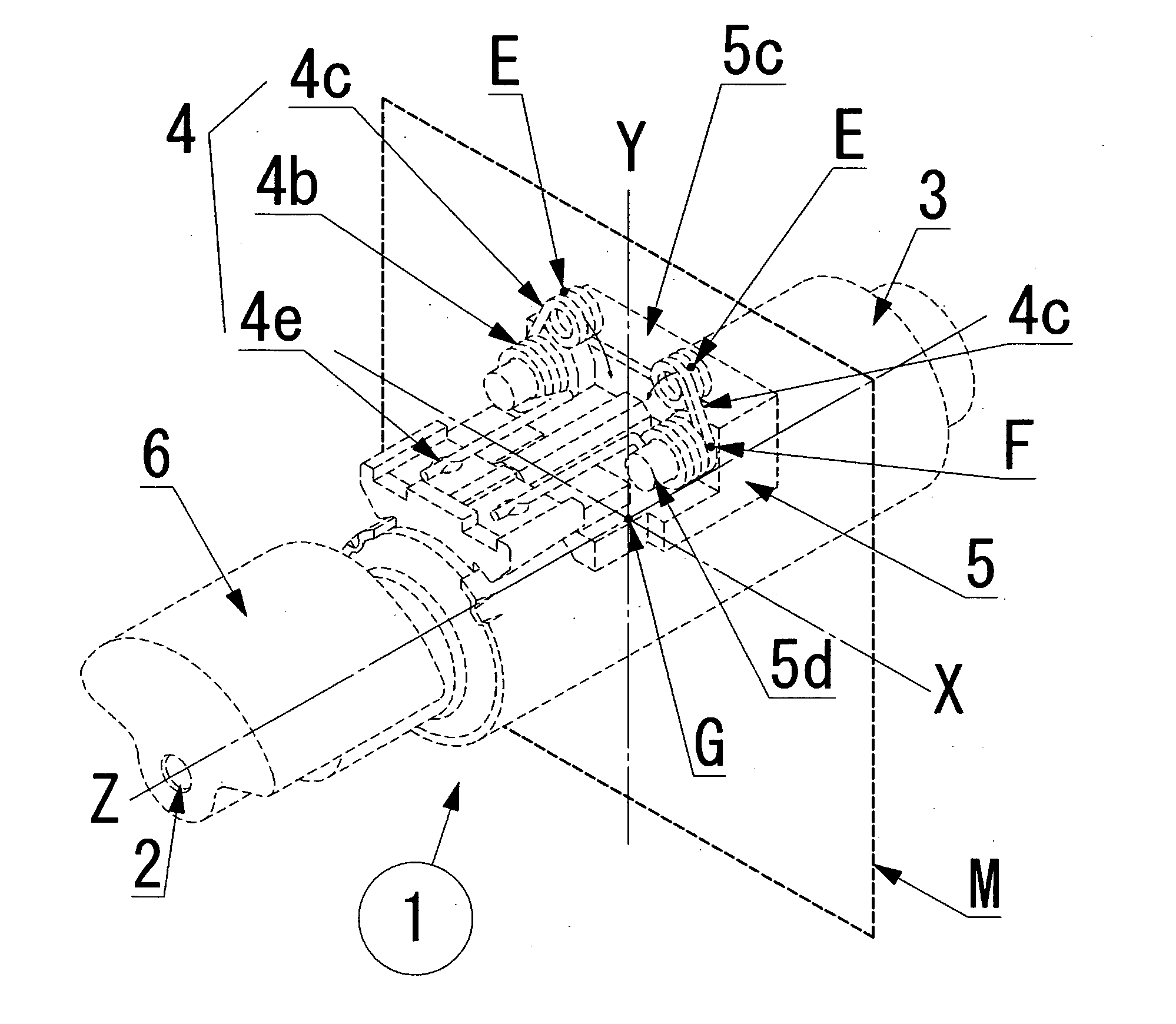
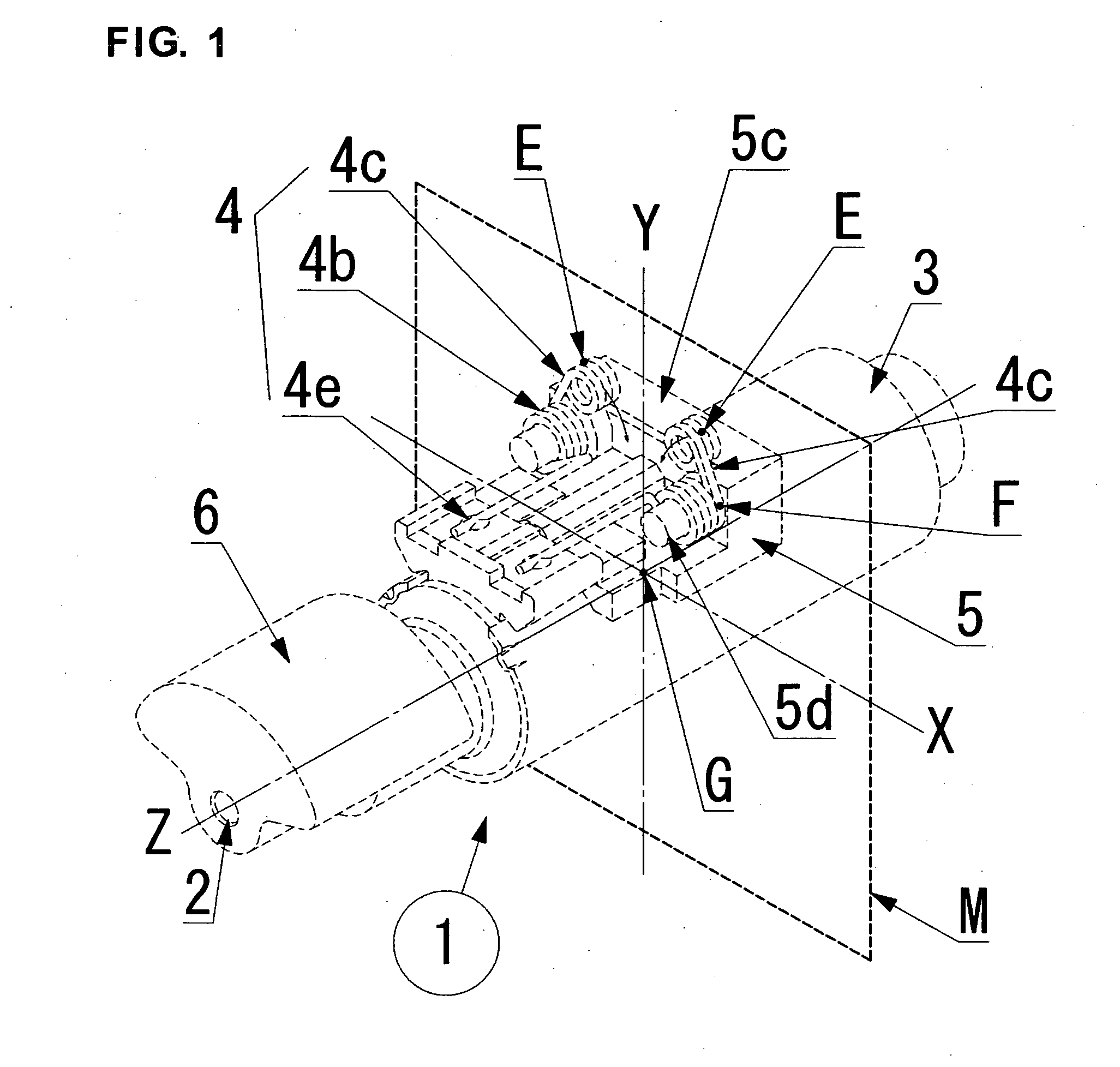
[0077] Now the structure of the first embodiment according to this invention is described referring to FIGS. 1 through 7. In this first embodiment, a cylindrical vibration motor of coreless type having a rotating shaft attached with an eccentric weight is taken as an example of a motor for generating vibration.

[0078]FIG. 1 shows a perspective view of an example of a preferred embodiment according to this invention. A vibration motor 1 according to this invention has a power supply terminal structure, wherein each of a bending point F and an action point E of a movable portion 4c movable 4e in the direction to be in contact with a power supply land of a power supply terminal 4 is arranged in a plane M (X-Y plane) that includes the gravity center G of vibrational motion of the aforementioned vibration motor 1 and is almost perpendicular to a rotating axis 2 of the aforementioned weight 6 as shown in FIG. 1.

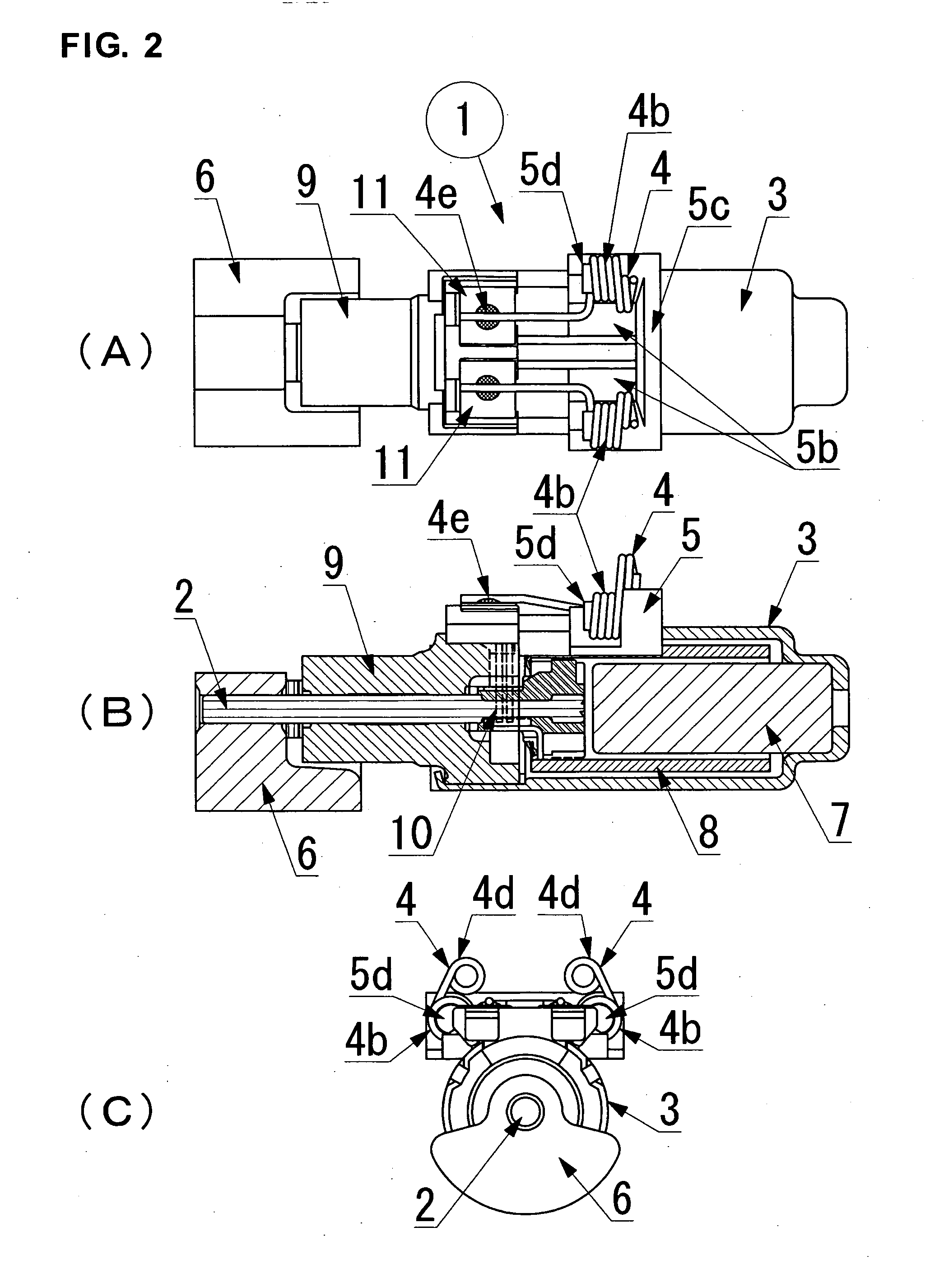
[0079]FIG. 2 (B) shows a schematic cross-sectional view of the interior of th...

second embodiment

[0093] Now the structure of the second embodiment according to this invention is described referring to FIGS. 8 through 11. By the way, the portions identical to those in the first embodiment are provided with the same item numbers and repetitive descriptions are omitted or simplified.

[0094] The points differing from the aforementioned first embodiment is that the power supply terminal consisting mainly of the aforementioned winding portion is modified to that having a shape of a torsion spring, that the ring-like tip end of the movable end of the power supply terminal is modified to a shape bent like a letter V as a shape for connecting, and that the arrangement of the internal structure of the coreless motor is modified. An inclining structure where a pair of power supply terminals inclines in the internal direction with each other is the same as the first embodiment.

[0095] In other words, the aforementioned pair of power supply terminals is made from torsion springs wherein a p...


PUM

PropertyMeasurementUnit
Angleaaaaaaaaaa
Angleaaaaaaaaaa
Weightaaaaaaaaaa

Abstract

[Problem] To realize high reliability and a long-term stabilized power supply (long lifetime) in the connection between a power supply terminal and a power supply land on a circuit board.
[Solution] A motor for generating vibration comprising a vibration generating mechanism having a rotating shaft attached with a weight, a housing case for accommodating at least a part of the aforementioned vibration generating mechanism, and a pair of power supply terminals protruding from the aforementioned housing for electrically connecting the power supply terminal to a power supply land by making the terminal elastically in contact with the power supply land of a power source side circuit board to be mounted in a housing of a portable apparatus and for supplying power to the aforementioned vibration generating mechanism, wherein each of a bending point and an action point of a movable portion of the power supply terminal movable in the direction in which the aforementioned power supply terminal contacts the aforementioned power supply land is arranged in a plane that includes a center of gravity of vibrational motion of the aforementioned motor for generating vibration and is almost perpendicular to the rotating axis of the aforementioned weight.

Description

TECHNICAL FIELD [0001] This invention relates to a device for generating vibration that is mainly mounted in a portable apparatus (including such electronic devices as a mobile phone, a PHS, a small wireless communications device, and other various portable information communications terminals) to perform a soundless alarm function, specifically to a power supply mechanism for a power supply land of a circuit board of a power source side in a housing of a portable apparatus and for the aforementioned motor for generating vibration held by the housing. BACKGROUND ART [0002] A sudden incoming ring tone of a portable apparatus may sometimes disturb others in, for example, a quiet public space such as an art gallery and a concert hall with many people in a room for important commercial negotiations or conferences. Therefore, a wireless alarm function using a device for generating vibration to report an incoming signal with sensible vibration is mounted in various portable apparatuses. [...

Claims


Application Information

Patent Timeline
IPC IPC(8): H02K5/22H02K7/06B06B1/04H02K5/00H02K5/24H02K7/075H04M1/00
CPCH02K5/225Y10T29/49204H02K7/061H02K5/22H02K7/065H02K7/075
Inventor UCHIUMI, HIDEHIROSUZUKI, TOSHIOAOYAGI, TOMOHIDEKOGAWA, TAKESHIMORITA, KAZUO
Owner NAMIKI SEIMITSU HOSEKI KK
Why Eureka
Try Eureka