Multi-Layer Piezoelectric Element and Method for Manufacturing the Same

a piezoelectric element and multi-layer technology, applied in the direction of generators/motors, mechanical equipment, machines/engines, etc., can solve the problems of significant deformation (displacement) of the multi-layer piezoelectric element, and achieve the reduction of residual stress between the piezoelectric layer and the internal electrode, increase the displacement amount of the multi-layer piezoelectric element, and high durability

Active Publication Date: 2007-12-06
KYOCERA CORP
View PDF3 Cites 43 Cited by
  • Summary
  • Abstract
  • Description
  • Claims
  • Application Information

AI Technical Summary

Benefits of technology

[0038] In the first multi-layer piezoelectric element of the present invention, since the bonding strength between the piezoelectric layer and the internal electrode is made weaker than the strength of the piezoelectric layer, the force of the internal electrode to clamp the piezoelectric layer can be decreased thus enabling it to increase the amount of displacement of the multi-layer piezoelectric element. Moreover, since the residual stress between the piezoelectric layer and the internal electrode can be decreased, it is made possible to provide a piezoelectric actuator having high durability and high reliability which maintains the amount of displacement constant during operation.
[0039] Also in the first multi-layer piezoelectric element of the present invention, the force of the internal electrode to clamp the piezoelectric layer can be made relatively small and the residual stress can be decreased, even when the internal electrode is formed from a metal of high hardness. As a result, change in the amount of displacement can be decreased during continuous operation, and the device temperature can be suppressed from rising too high when the multi-layer piezoelectric element with the large residual stress is operated over a long period of time. This makes it possible to prevent thermal excursion from occurring that would otherwise occur when the device temperature becomes too high to control by heat dissipation, thereby preventing the amount of displacement from deteriorating.
[0040] In the second multi-layer piezoelectric element according to the present invention, the clamping force of the internal electrodes to restrict the piezoelectric layer from making displacement under an electric field is decreased by forming voids in the internal electrode with a proportion of the area occupied by the voids to the total area of a cross section of the internal electrode in a range from 5 to 70%. This enables the piezoelectric layer to easily deform so that a larger amount of displacement can be achieved, and the stress generated in the internal electrode is mitigated, thus achieving higher durability.
[0041] In the third multi-layer piezoelectric element according to the present invention, since the voids are formed so as to penetrate through the internal electrode in the direction of stacking, the clamping force of the internal electrodes to restrict the piezoelectric layer from making displacement under an electric field is decreased. This enables the piezoelectric layer to easily deform resulting in a larger amount of displacement, and the stress generated in the internal electrode is also mitigated so that higher durability is achieved.
[0042] In the fourth multi-layer piezoelectric element according to the present invention, since the portion where the internal electrodes of different polarities that overlap each other via the piezoelectric layer is formed in a configuration which does not have line symmetry, the stacked layers are suppressed from peeling off even when the multi-layer piezoelectric element undergoes continuous dimensional change of the device during operation. Also because resonance which occurs when the displacement takes place similarly can be suppressed, not only the occurrence of beat tone can be prevented but also the generation of harmonics signal can be prevented. Thus it is made possible to suppress noise from affecting the control signal and suppress the actuator from malfunctioning.
[0043] Also because the internal electrodes of different polarities are exposed on all the device side faces, stress generated in the device when operated as an actuator can be propagated to the outside of the device, thus it is made possible to provide a piezoelectric actuator having high durability and high reliability.

Problems solved by technology

However, unlike the conventional multi-layer electronics components (multi-layer ceramic capacitor, etc.), the multi-layer piezoelectric element experiences a significant deformation (displacement) of the piezoelectric porcelain under an electric field when electric power is supplied.

Method used


Image

  • Multi-Layer Piezoelectric Element and Method for Manufacturing the Same
  • Multi-Layer Piezoelectric Element and Method for Manufacturing the Same
  • Multi-Layer Piezoelectric Element and Method for Manufacturing the Same

Examples


first embodiment

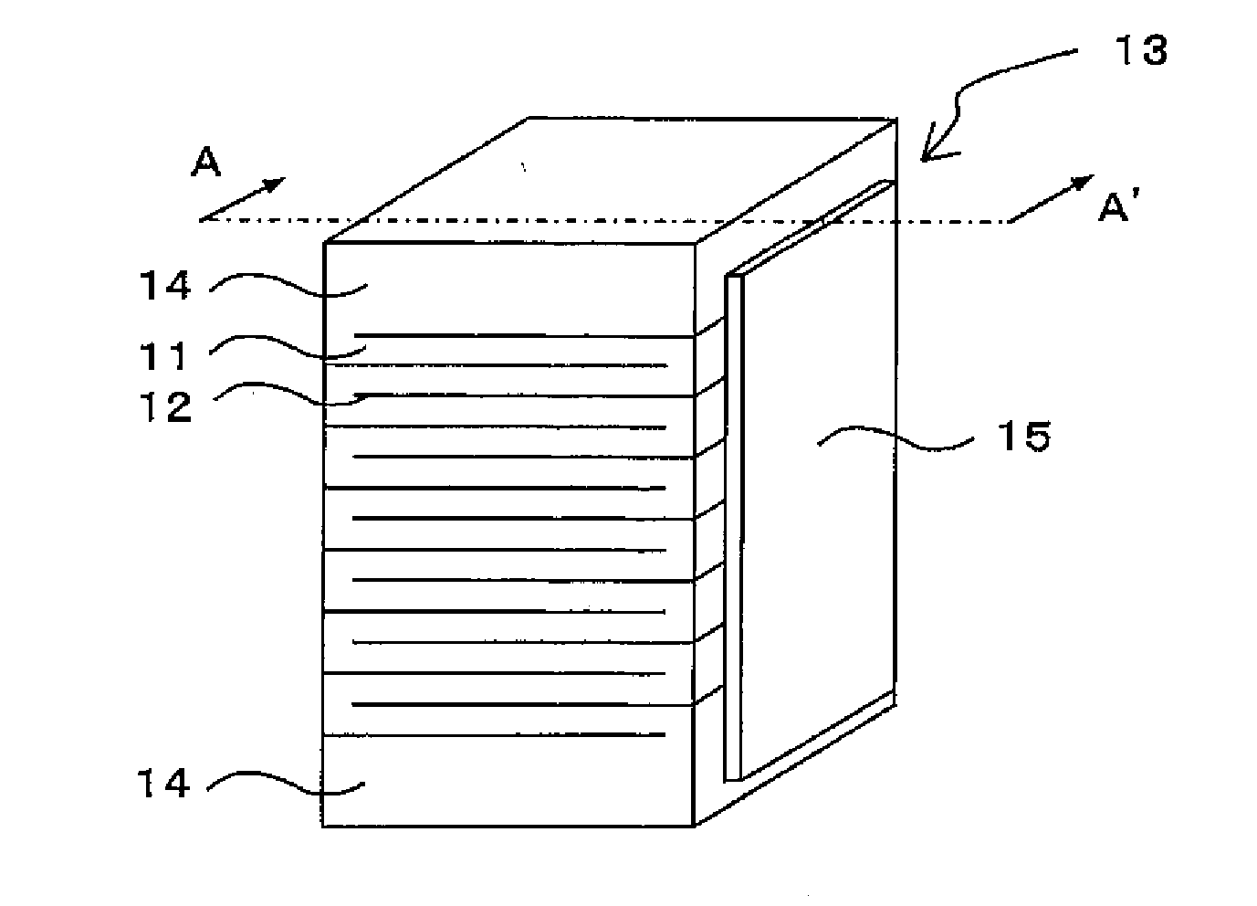
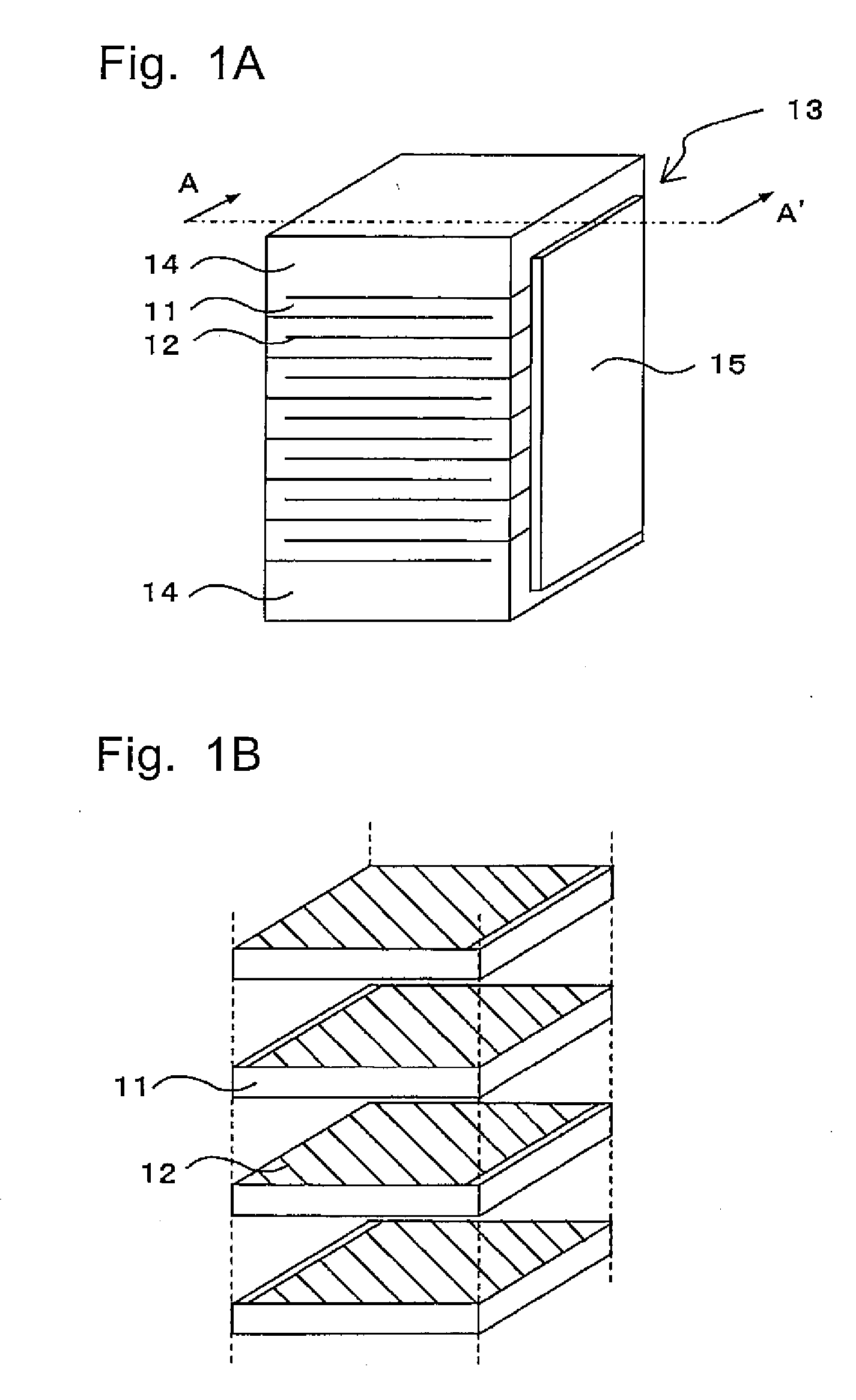
[0130]FIG. 1 shows the constitution of the multi-layer piezoelectric element according to the first embodiment of the present invention, where FIG. 1A is a perspective view thereof, and FIG. 1B is an exploded perspective view showing the constitution of stacking piezoelectric layer and internal electrode layers.

[0131] In the multi-layer piezoelectric element according to the first embodiment, as shown in FIG. 1A and FIG. 1B, the external electrodes are formed on a pair of opposing side faces of a stack 13 constituted from the piezoelectric layer 11 and the internal electrodes 12 placed alternately one on another, and the internal electrodes 12 are connected to the external electrodes 15 in every other layer. That is, the internal electrode 12 is exposed on the side face of the stack where the external electrodes 15 is formed, and the external electrode 15 is connected to the exposed internal electrode 12 so as to establish electrical continuity. On both ends of the stack 13 in the ...

second embodiment

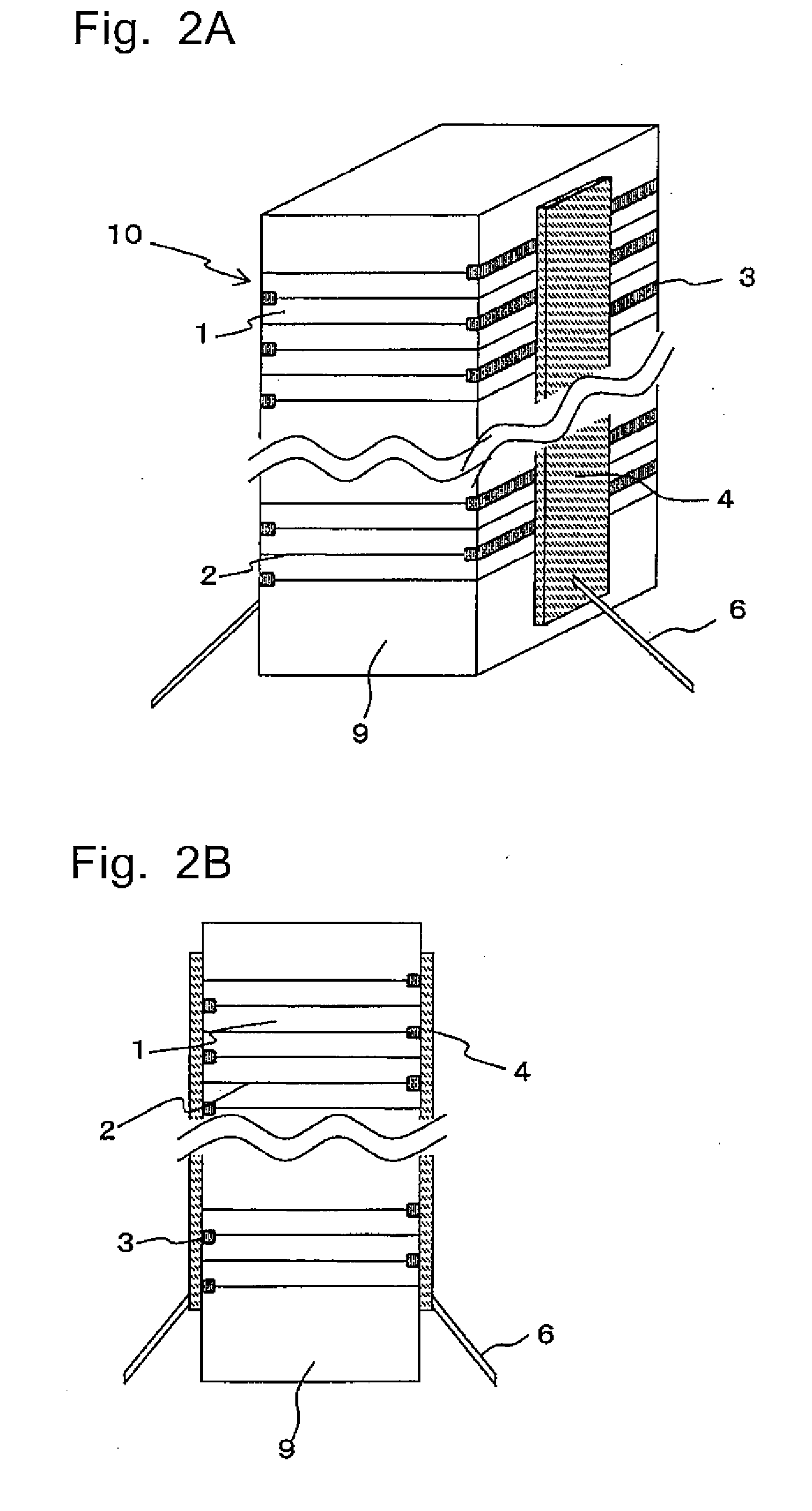
[0164]FIGS. 2A and 2B show the constitution of the multi-S layer piezoelectric element according to second embodiment of the present invention, where FIG. 2A is a perspective view and FIG. 2B is a sectional view. FIG. 3 is an enlarged sectional view of a portion near the internal electrode of the multi-layer piezoelectric element shown in FIG. 2.

[0165] The multi-layer piezoelectric element 10 according to the second embodiment is characterized in that the internal electrode 2 has controlled voids 20, and has a structure substantially similar to that of the multi-layer piezoelectric element of the first embodiment with other respects.

[0166] That is, as shown in FIG. 2, the multi-layer piezoelectric element 10 according to the second embodiment has such a constitution as the external electrodes 4 are formed on a pair of opposing side faces of a stack which is formed by stacking the piezoelectric layers 1 and the internal electrodes 2 alternately, while the external electrodes 4 are ...

third embodiment

[0193] The multi-layer piezoelectric element according to third embodiment of the present invention will now be described. FIGS. 5A and 5B show the constitution of the multi-layer piezoelectric element according to the third embodiment, where FIG. 5A is a perspective view and FIG. 5B is an exploded perspective view showing the piezoelectric layers and the internal electrodes being stacked one on another. FIGS. 6A and 6B are enlarged view showing the internal electrode pattern of the multi-layer piezoelectric element according to the third embodiment, where FIG. 6A is an exploded perspective view showing the piezoelectric layers and the internal electrodes being stacked one on another, and FIG. 6B is a projection view showing a portion 82a where the internal electrode and the external electrode of different polarities overlap via the piezoelectric layer 11

[0194] The multi-layer piezoelectric element of the third embodiment has the internal electrode and the external electrode which a...


PUM

PropertyMeasurementUnit
distanceaaaaaaaaaa
thicknessaaaaaaaaaa
temperatureaaaaaaaaaa

Abstract

A multi-layer piezoelectric element having high durability which allows it to increase the amount of displacement of a piezoelectric actuator under high voltage and high pressure and does not undergo a change in the amount of displacement during continuous operation in a high electric field and under a high pressure over a long time period is provided. The multi-layer piezoelectric element comprises a stack of at least one piezoelectric layer and a plurality of internal electrodes consisting of first and second internal electrodes placed one on another, a first external electrode formed on a first side face of the stack and connected to the first internal electrode and a second external electrode formed on a second side face of the stack and connected to the second internal electrode, wherein the bonding strength between the piezoelectric layer and the internal electrode is weaker than the bending strength of the piezoelectric layer.

Description

TECHNICAL FIELD [0001] The present invention relates to a multi-layer piezoelectric element (may be hereinafter referred to simply as an “element”) and an injection apparatus, for example, fuel injection apparatus of automobile engine, liquid injection apparatus of ink jet printer or the like, or a drive unit used in precision positioning device or vibration preventing device for an optical apparatus, and to a multi-layer piezoelectric element used as a sensor element mounted in combustion pressure sensor, knocking sensor, acceleration sensor, load sensor, ultrasound sensor, pressure sensor, yaw rate sensor or the like, or used as a circuit component mounted in piezoelectric gyro, piezoelectric switch, piezoelectric transducer, piezoelectric breaker or the like. BACKGROUND ART [0002] Multi-layer piezoelectric actuators constituted from piezoelectric layers and internal electrodes stacked alternately one on another have been known. The multi-layer piezoelectric actuators can be divid...

Claims


Application Information

Patent Timeline
Patent Type & Authority Applications(United States)
IPC IPC(8): H01L41/083H01L41/22F02M51/06F02M51/00H01L41/047H01L41/187H01L41/273H02N2/00
CPCH01L41/0471H01L41/0472Y10T29/42H01L41/273H01L41/0477H10N30/872H10N30/871H10N30/877H10N30/053
Inventor KONDO, MITSUOTERAZONO, MASAKIOKAMURA, TAKESHISAKAUE, KATSUSHI
Owner KYOCERA CORP
Why Eureka
Try Eureka