
Spectrometry Diagnostic Electronic Circuit and Associated Counting System

a technology of electronic circuit and counting system, applied in the direction of neutron radiation measurement, frequency analysis, instruments, etc., can solve the problems of calibration errors, measurement signals are not available in real time, and it is impossible to distinguish any piles

Inactive Publication Date: 2007-12-06
COMMISSARIAT A LENERGIE ATOMIQUE ET AUX ENERGIES ALTERNATIVES
View PDF4 Cites 8 Cited by
  • Summary
  • Abstract
  • Description
  • Claims
  • Application Information

AI Technical Summary

Benefits of technology

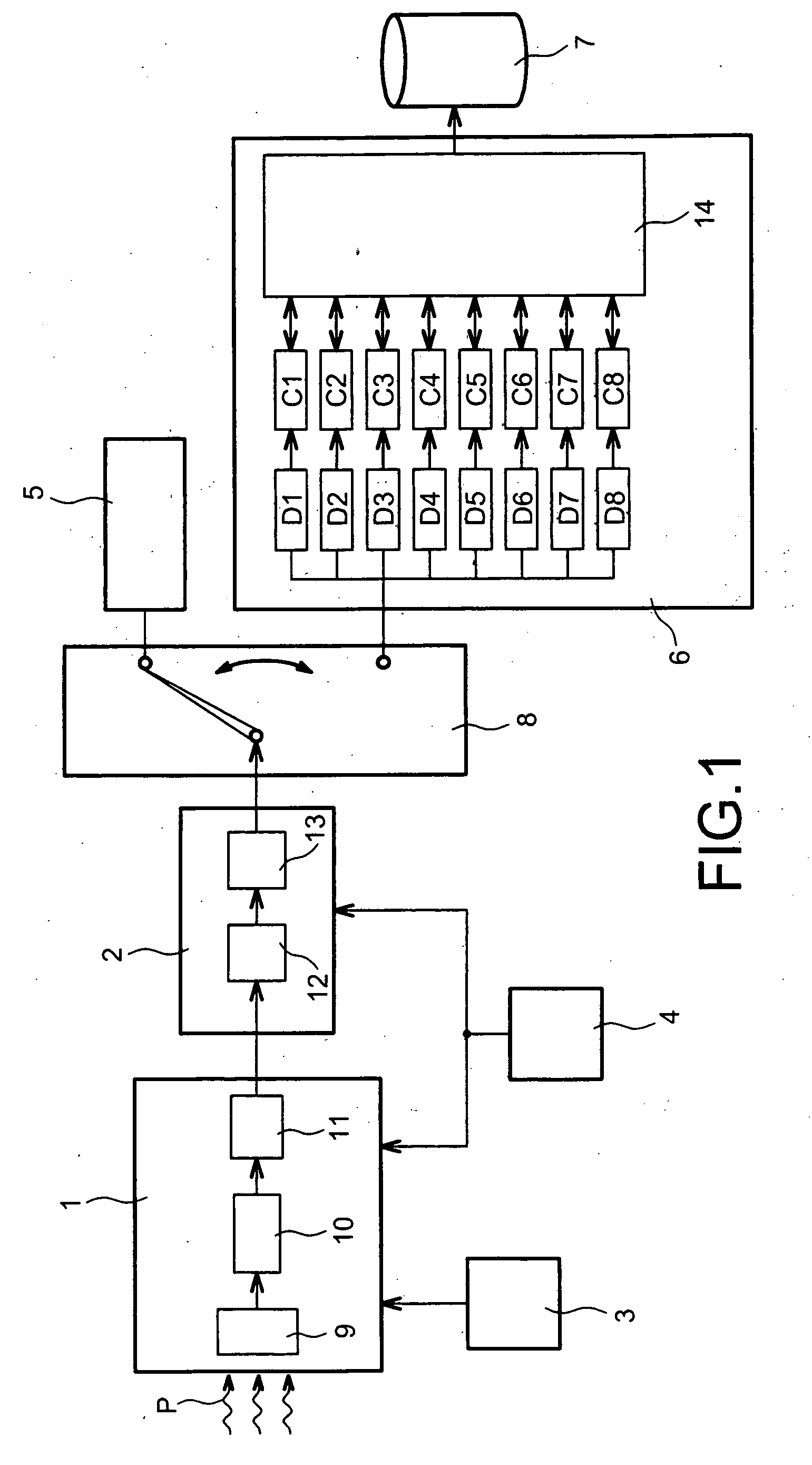
[0028] The pulse rejection means of the diagnostic electronic circuit according to the invention have many advantages. When combined with the calibration means according to the invention, they enable the use of an in situ calibration without disassembling or disconnecting the measurement system, which very significantly reduces risks of errors. It is then possible to perform high quality calibrations in a hostile medium in a routine manner. The calibration may relate to all sight channels. Also, in combination with the sorting and counting means according to the invention, the pulse rejection means according to the invention can be used to implement real time discrimination and counting of the detected pulses. Real time measurement of the detected pulses has the main advantage that a suitable program can be used to obtain a local emissivity profile by inversion of real time data using an Abel method. Suprathermal profiles can then be slaved, consequently enabling direct control over the current profile, which satisfies the fixed objective for an “advanced tokamak”.

Problems solved by technology

Firstly there is no information concerning the input signal, so that the shaped pulse cannot be displayed and it becomes impossible to distinguish any piling up following the simultaneous arrival of two photons on the detector.
Then, the measured signals are not available in real time which prevents any profile inversion in real time and consequently slaving of the deposited power of the hybrid wave and slaving of the current profile.
This can result in calibration errors.
Furthermore, this disconnection increases the manipulations made on the system and consequently the risks of damaging it.

Method used


Image

  • Spectrometry Diagnostic Electronic Circuit and Associated Counting System
  • Spectrometry Diagnostic Electronic Circuit and Associated Counting System
  • Spectrometry Diagnostic Electronic Circuit and Associated Counting System

Examples


Embodiment Construction

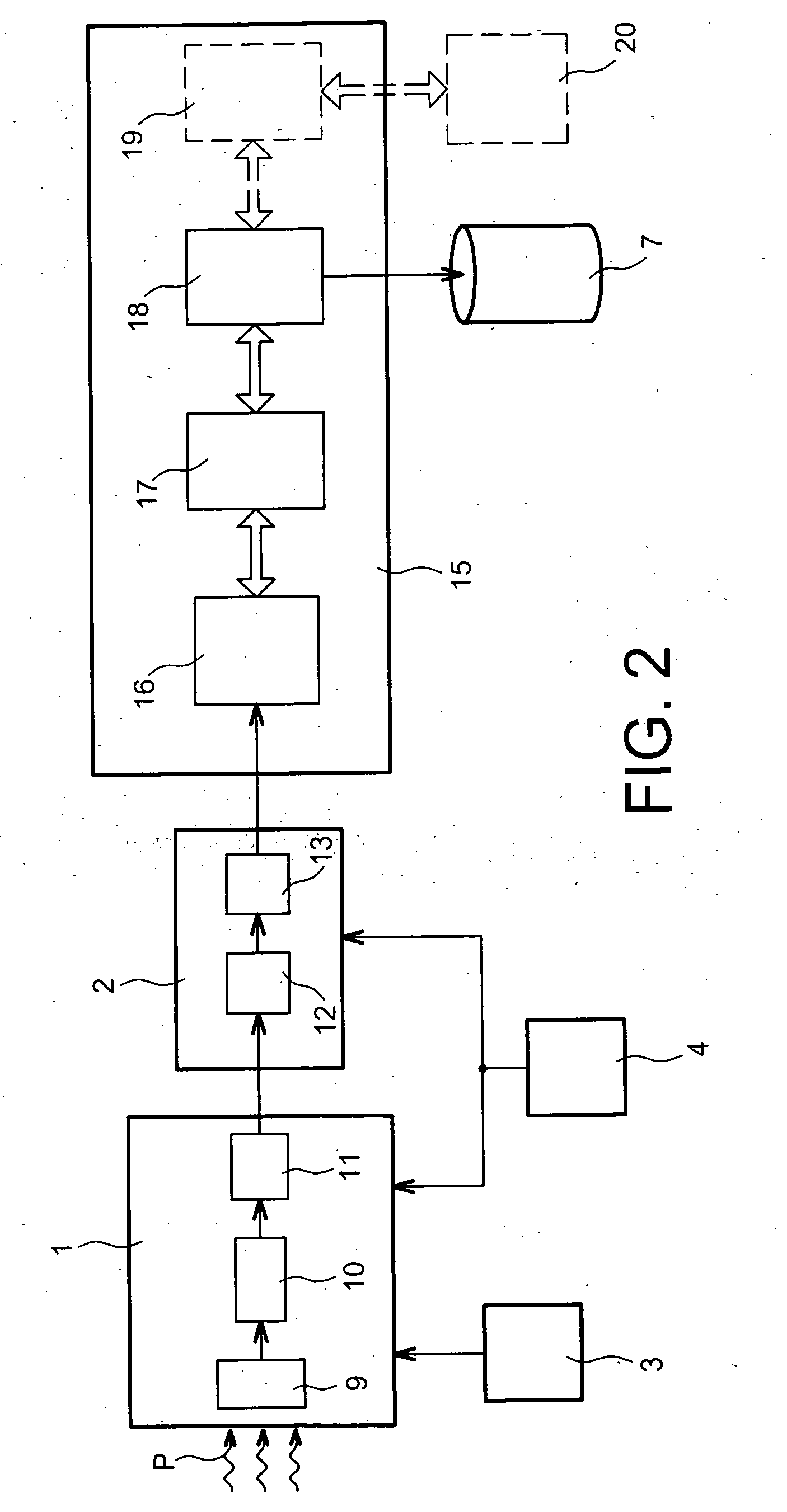
[0038]FIG. 2 shows a spectrometry diagnostic measurement system based on radiation, for example of hard X-rays, according to the invention, for one channel.

[0039] The measurement system includes a camera 1, a reception chassis 2, a bias circuit 3, a power supply circuit 4, a data processing circuit 15 and a data storage unit 7. The measurement system according to the invention is different from the measurement system according to prior art due to the data processing circuit 15. The data processing circuit 15 includes a diagnostic electronic circuit 16 according to the invention in series with a data acquisition and processing unit 17 and a management unit 18. According to one improvement to the invention, the data processing circuit 15 may also contain a shared RAM 19. The shared RAM 19, for example a SCRAMNET (Shared Common Random Access Memory Network) card can then advantageously be used to share data with other acquisition units through a communication network 20.

[0040]FIG. 3 ...


PUM


Abstract

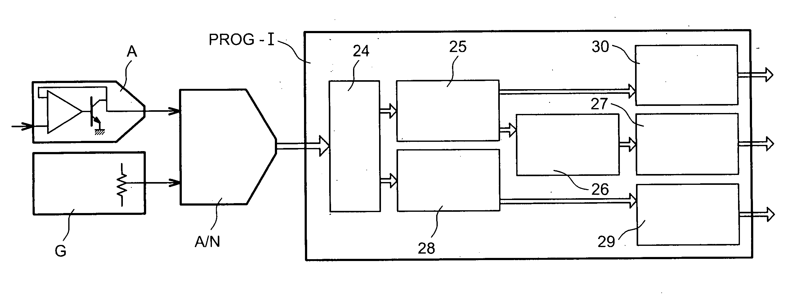
The invention relates to a spectrometry diagnostic electronic circuit comprising digital data detection means corresponding to detected pulses and amplitude measurement means to associate a measured amplitude with a detected pulse (24) , wherein pulse rejection means (25) are used to detect digital data and reject every pulse with a width that exceeds a pulse width threshold (tc) and any new pulse during a programmed time interval (T3), if a first pulse has been detected during the programmed time interval.

Description

TECHNICAL FIELD AND PRIOR ART [0001] This invention relates to a spectrometry diagnostic electronic circuit. [0002] The invention also relates to a particle counting system that includes a spectrometry diagnostic electronic circuit according to the invention. For example, the counting system may be a neutron counting system for a controlled nuclear fusion or fission reactor. [0003] Controlled nuclear fusion is an attractive and inexhaustible alternative solution for the generation of electricity. The purpose of controlled fusion is to reproduce energy produced by the sun on earth. The energy is then produced inside a device commonly called a tokamak. A tokamak is a device that powerfully confines a very hot ionised gas ring called plasma, by the combined action of a strong magnetic field and an intense electric current of a few mega-amperes. The plasma develops deuterium / tritium fusion reactions within its body producing neutrons that carry energy. Optimisation of physical, technolo...

Claims


Application Information

Patent Timeline
Patent Type & Authority Applications(United States)
IPC IPC(8): G01R29/027G01T1/17G01T3/00
CPCG01T3/001G01T1/17Y02E30/10
Inventor JOUVE, MICHELMAZON, DIDIER
Owner COMMISSARIAT A LENERGIE ATOMIQUE ET AUX ENERGIES ALTERNATIVES
Learn More