Control apparatus, control method and monitoring control system

a control apparatus and control method technology, applied in the direction of program control, electric programme control, instruments, etc., can solve the problems of reducing unable to significantly reduce the number of cables, and the control device cannot be made into an autonomous distributed type, etc., to prevent communication failure, reduce the size of the facility, and continue stable control

Inactive Publication Date: 2007-12-06
HITACHI LTD
View PDF11 Cites 26 Cited by
  • Summary
  • Abstract
  • Description
  • Claims
  • Application Information

AI Technical Summary

Benefits of technology

[0011]Furthermore, recently, with increase of the plant scale and the sophistication of the control system, the number of I / O parts of the control device tends to increase, which in turn increase the installation cost. A system easily compatible with extension of a device and an apparatus is desired.
[0027]Moreover, each control / measurement apparatus includes an operation circuit to become programmable and the protection interlock or the control logic is built in so as to obtain an autonomous distributed system. Accordingly, even if the radio communication with the control device is cut off, it is possible to continue stable control.

Problems solved by technology

However, in the case of the field bus, there is a problem that if a trouble such as disconnection occurs at a certain point of a segment, all the transmissions to the control apparatuses and measurement apparatuses connected to the downstream side (apparatus side) from the disconnected point are disabled.
Accordingly, even in a large-scale steam-power generation station using tens of thousands of I / O points, the field bus can be applied only for systems of less importance and cannot significantly reduce the number of cables.
Moreover, since the conventional control apparatus does not have means for performing a complicated process, control and protection logic of each control apparatus is defined at the control device side for performing operation.
Furthermore, in the conventional field bus method, the number of control apparatuses and measurement apparatuses which can be connected to one segment is limited to a certain number and only a small number of signals can be transmitted and received between one control apparatus to / from the control device and other control apparatus.
Thus, the control device cannot be made into an autonomous distributed type.
However, the autonomous distributed degree is such that control cannot be performed without an instruction from the control device.
Furthermore, recently, with increase of the plant scale and the sophistication of the control system, the number of I / O parts of the control device tends to increase, which in turn increase the installation cost.

Method used


Image

  • Control apparatus, control method and monitoring control system
  • Control apparatus, control method and monitoring control system
  • Control apparatus, control method and monitoring control system

Examples


first embodiment

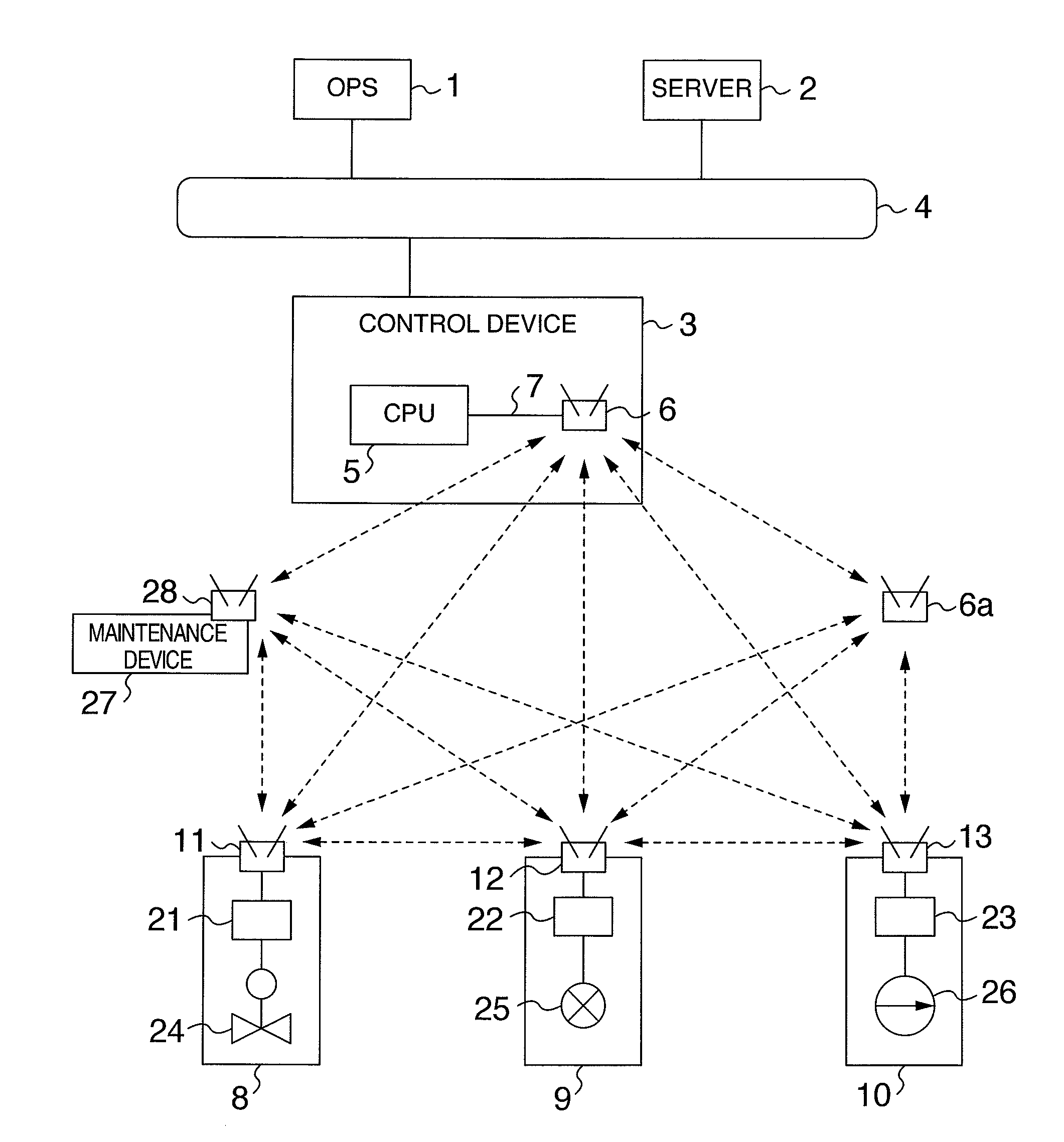
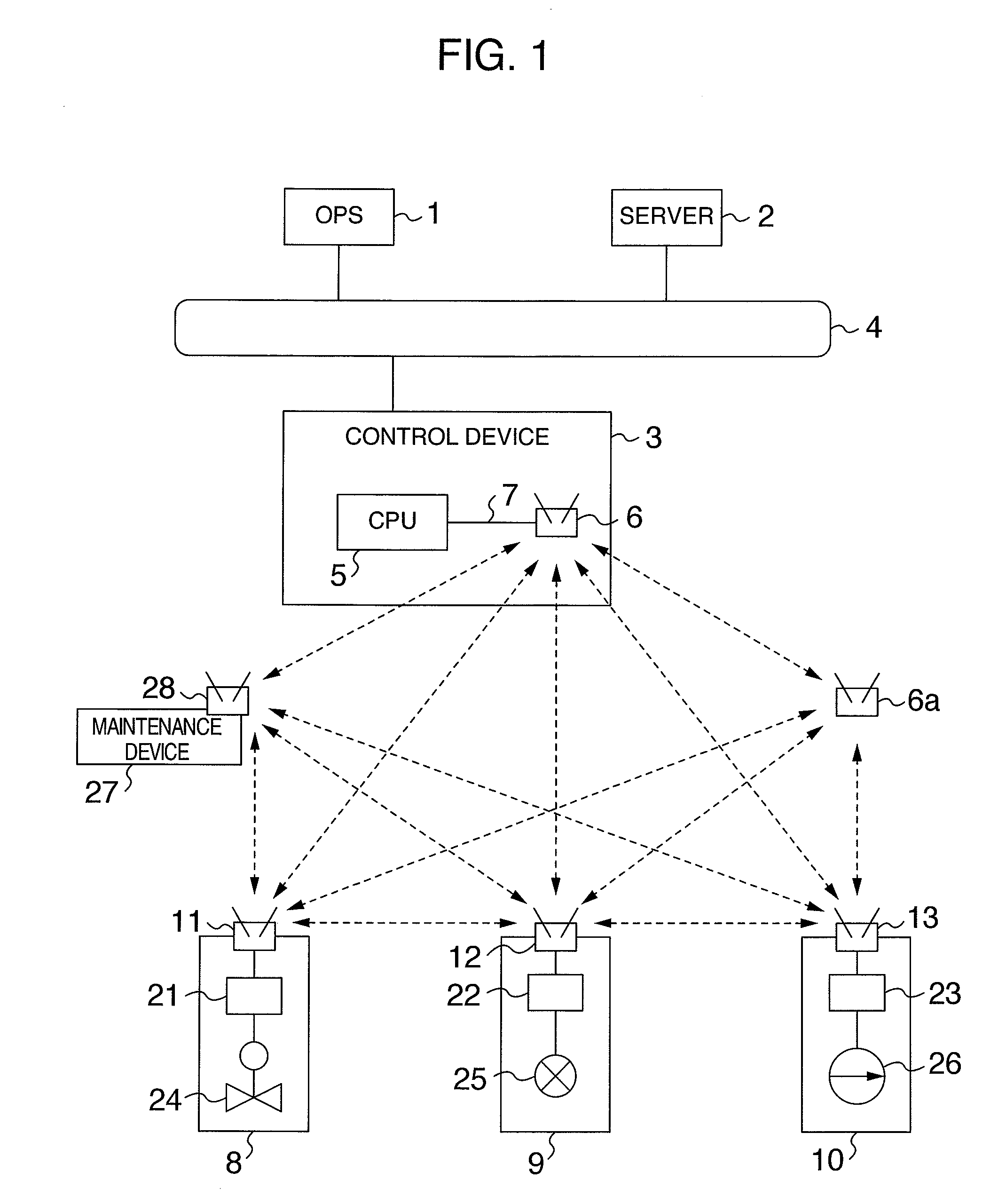
[0036]Firstly, referring to FIG. 1, explanation will be given on the entire configuration of the system according to the present invention. The system includes an operation device (hereinafter, referred to as OPS) 1, a server 2, a control device 3, a control apparatus, and a measurement apparatus. The OPS 1, the server 2, and the control device 3 are arranged in a central control room and they are connected to one another via a network 4. In general, a plurality of sets of the control device 3 are installed for each control system. However, in FIG. 1, only one set is shown. The OPS 1 is a human-machine interface device having an operation / monitoring function required for operation of the plant. The OPS 1 outputs an instruction to each control apparatus according to a request by an operator, displays plant information on a display device such as a CRT, provides various control information to the operator, and outputs a guidance. The server 2 performs information processing concerning...

second embodiment

[0062]Referring to FIG. 4, explanation will be given on the entire configuration example of the system according to the This embodiment includes an operation device (hereinafter, referred to OPS) 201, a server 202, a control device 203, a control apparatus, and a measurement apparatus. The OPS 201, the server 202, and the control device 203 are installed in the central control room or the like and they are connected to one another via a network 204. In general, a plurality of sets of the control device 203 are installed for each control system but in FIG. 4, only one set 201 is shown. The OPS 201 is a human-machine interface device having the operation / monitoring function required for operation of the plant. The OPS 201 outputs an instruction for each control apparatus to the control device 203 according to a request from an operator, displays plant information to a display device such as a CRT, provides various types of control information to the operator, and outputs guidance. Th...


PUM


Abstract

A control device includes a CPU generating a control instruction for a control apparatus according to an instruction inputted from an OPS or a server and a radio communication unit performing a radio communication with each of the control apparatuses and measurement apparatuses. The control and the measurement apparatuses include a radio communication unit for performing a radio communication with the control device and other control and the measurement apparatus, and an operation circuit for performing a control and protection operation process. The operation circuit operates and controls a control signal according to a control instruction inputted from the control device, logic of the protection interlock and the control logic stored in the operation circuit, and process data on the control apparatus and other associated control and measurement apparatus, thereby monitoring and controlling a plant.

Description

INCORPORATION BY REFERENCE[0001]The present application claims priorities from Japanese applications JP2006-150199 filed on May 30, 2006, JP2006-249508 filed on Sep. 14, 2006, the contents of which are hereby incorporated by reference into this application.BACKGROUND OF THE INVENTION[0002]The present invention relates to a monitoring control system or the like for operating a plant by monitoring and controlling a control apparatus and in particular, to a monitoring control system appropriate for monitoring and controlling various control apparatuses in a water power generation, steam power generation, and atomic power generation plant and a control apparatus and a control method used in the system.[0003]In a generation plant, computers such as an operation device and a server are arranged in a central control room and these are connected to control devices such as a main turbine control device and a boiler local control device via a network so as to constitute a system for operating...

Claims


Application Information

Patent Timeline
Patent Type & Authority Applications(United States)
IPC IPC(8): G05B19/18G05B13/02G06F17/00
CPCG05B2219/31455G05B19/0423G05B2219/33192
Inventor YAMADA, TAKAHIRONISHIOKA, ATSUSHIMARUYAMA, YOSHIO
Owner HITACHI LTD
Why Eureka
Try Eureka