Sensor network system, gateway node, and method for relaying data of sensor network system

a sensor network and gateway node technology, applied in the field gateway nodes, and methods for relaying data of sensor network systems, can solve the problems of large amount of labor required for the development and maintenance of application software, large amount of labor required to make the definitions of the outputs of the sensor nodes identical, and difficulty in sharing information between multiple sensor network systems, so as to reduce the load of wireless networks, improve usability, and facilitate data in a server

Inactive Publication Date: 2007-12-06
ODAKA TOSHIYUKI +3
View PDF21 Cites 90 Cited by
  • Summary
  • Abstract
  • Description
  • Claims
  • Application Information

AI Technical Summary

Benefits of technology

[0018] Therefore, according to this invention, preset meaning information is added to sensing data received from a wireless network and then the sensing data is transmitted to a wired network, thereby making it possible to reduce the load of the wireless network where there are many restrictions on resources and improve the usability thereof. In addition, since the data is rich in information, it becomes extremely easy to use the data in a server and an application on a user computer. Further, since the sensing data stored in the server includes the meaning information added by a gateway (base station), the sensing data can easily be used from an application on the user computer without applying any process to the sensing data in the server, and the development and the maintenance of an application can easily be performed.

Problems solved by technology

However, the above-mentioned conventional sensor network system has a problem in that just one sensor network system can handle outputs of the sensor node, so it is difficult for multiple sensor network systems to share information of the sensor node.
However, a large amount of labor is required to make the definitions identical of the outputs of the sensor nodes in all the pieces of application software.
Thus, a large amount of labor is required for the development and the maintenance of application software.
Thus, it is difficult to use the output of the sensor node in the multiple sensor network systems.
In contrast, when the sensor node adds detailed information to sensing data and transmits the sensing data as in the conventional technique, the power consumption is increased as the amount of data to be transmitted is increased, which reduces the lifetime of the battery.
In addition to this, in a case where a large number of sensor nodes are used, when one sensor node performs redundant communication, the use efficiency is reduced in a limited wireless communication band.

Method used


Image

  • Sensor network system, gateway node, and method for relaying data of sensor network system
  • Sensor network system, gateway node, and method for relaying data of sensor network system
  • Sensor network system, gateway node, and method for relaying data of sensor network system

Examples


first embodiment

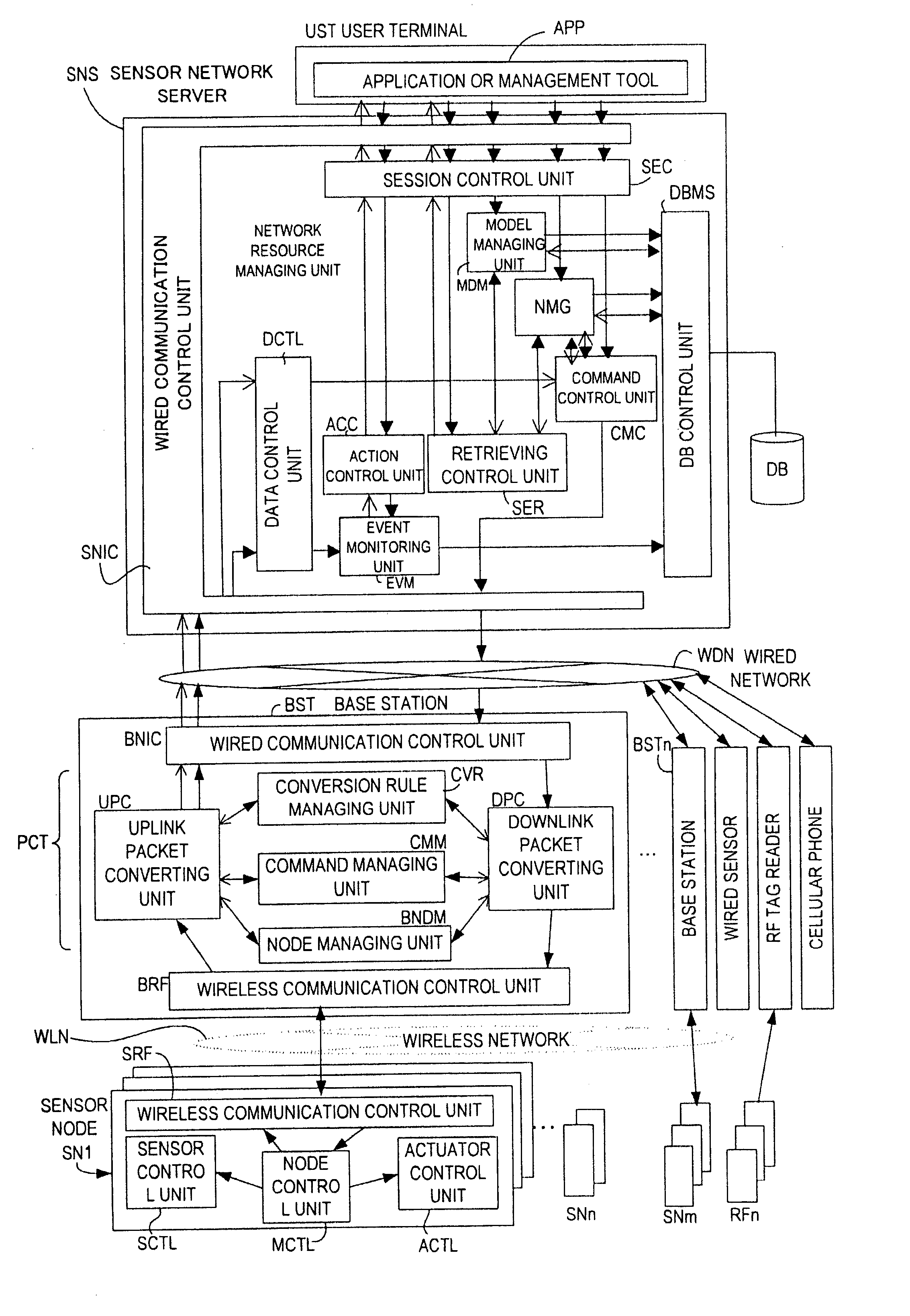
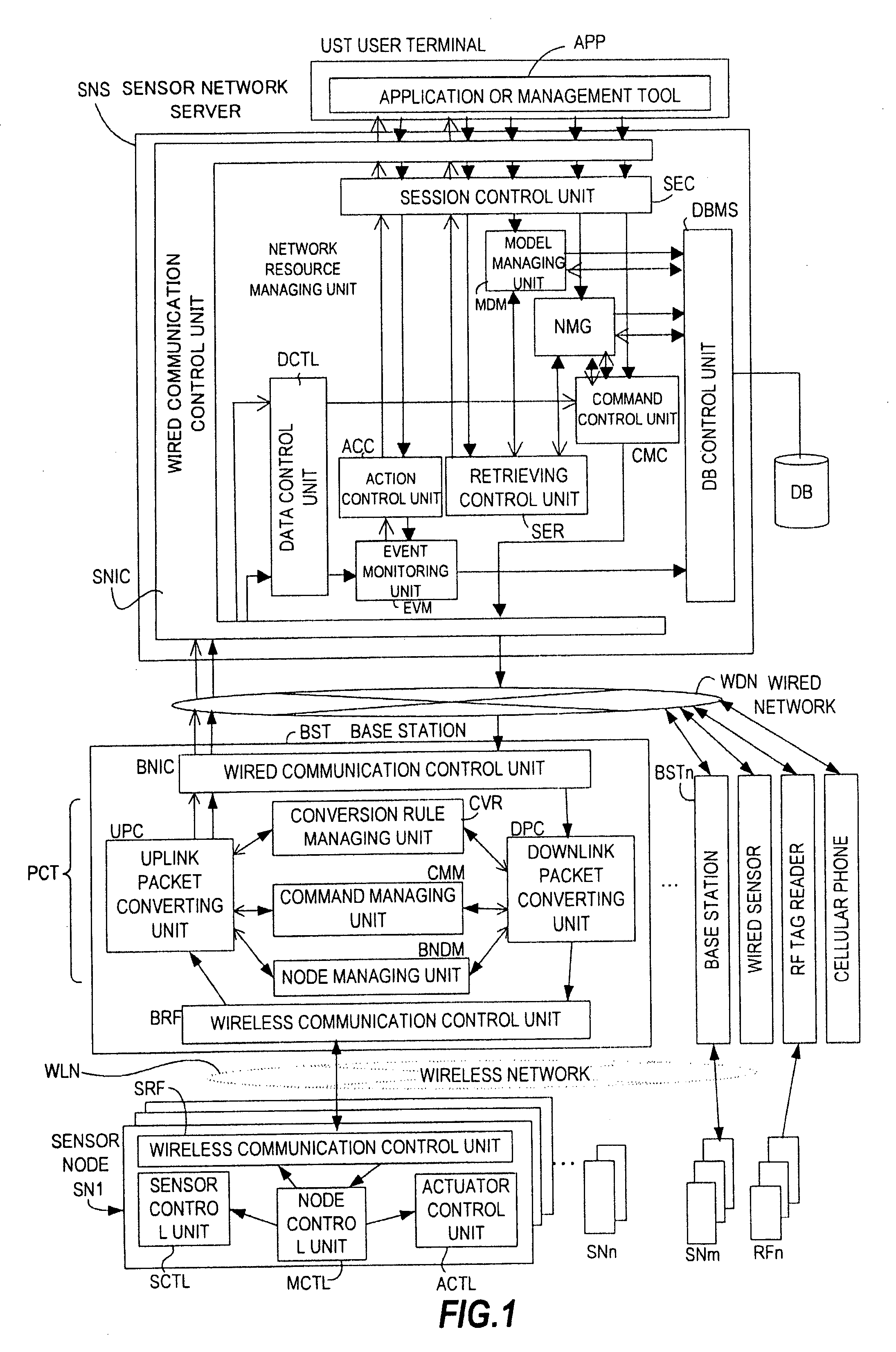
[0036]FIG. 1 is a block diagram showing an example of a sensor network system according to a first embodiment of this invention. In the sensor network system shown in FIG. 1, sensing data received from sensor nodes SN1 to SNn is transmitted to a base station BST by wireless communication. The base station BST functions as a gateway of the sensor network system to add meaning information to the sensing data. The sensing data to which the meaning information is added by the base station BST is transmitted to a sensor network server SNS via a wired network WDN and used by a user terminal UST.

(Sensor Node)

[0037] The sensor nodes SN1 to SNn shown in FIG. 1 each output sensing data or a preset identifier (ID) by wireless communication. The sensor nodes SN1 to SNn are attached, for example, to predetermined portions of a user for the purpose of monitoring a status of the user. The sensor nodes SN1 to SNn perform wireless communication with the base station BST via a wireless network WLN...

second embodiment

[0131]FIG. 15 shows an example of using sensing data by a large number of sensor network systems, according to a second embodiment.

[0132] A wired network WDN0 is connected to multiple user terminals UST1 and UST2 and to multiple sensor network systems # 1 to #4. The user terminal UST1 runs an application A that uses sensing data of the multiple sensor network systems # 1 to #4. The user terminal UST2 runs an application B that uses the sensing data of the multiple sensor network systems #1 to #4.

[0133] A sensor network system #1 is configured in the same way as the sensor network system of the first embodiment, in which a sensor network server SNS-1 is connected to a base station BST1-1 via a wired network WDN1 and there are a large number of sensor nodes SN1-1 to SN1-N controlled by the base station BST1-1. As in the first embodiment, the base station BST1-1 adds meaning information to an uplink packet PWD destined for the sensor network server SNS-1 and also adds a global ID, wh...


PUM


Abstract

Provided is a method for transferring data of a sensor network system in which communication is made with multiple sensor nodes SN1s connected via a wireless network to transmit sensing data measured by the sensor nodes SN1s to a server SNS connected via a wired network. The method includes: receiving the sensing data from each of the sensor nodes SN1s (S1); adding meaning information that corresponds to a measurement value contained in the sensing data to the sensing data (S2, S5); and transmitting the sensing data to which the meaning information is added to the server SNS (S6). Accordingly, data of the sensor nodes are efficiently used by multiple applications while effectively using a reduced resource for wireless communication.

Description

[0001] This application is a continuation application of U.S. application Ser. No. 11 / 566,367, filed Dec. 4, 2006, the entirety of which is incorporated herein by reference. CLAIM OF PRIORITY [0002] The present application claims priority from Japanese application JP2005-350342 filed on Dec. 5, 2005, the content of which is hereby incorporated by reference into this application.BACKGROUND [0003] This invention relates to a technique of using information transmitted from a large number of sensors connected to a network. [0004] In recent years, a network system (hereinafter, referred to as sensor network system) has been studied in which a compact electronic circuit having a wireless communication function is added to a sensor to retrieve various types of information used in the physical world into an information processor. A wide range of applications to the sensor network system are examined. For example, a technique is proposed in which biological information such as pulse, positio...

Claims


Application Information

Patent Timeline
Patent Type & Authority Applications(United States)
IPC IPC(8): G06F15/173
CPCH04L12/2825H04L2012/2841H04L67/28H04L67/12H04L67/2823H04L67/56H04L67/565
Inventor ODAKA, TOSHIYUKIMORIWAKI, NORIHIKOOGUSHI, MINORUARA, KOJI
Owner ODAKA TOSHIYUKI
Why Eureka
Try Eureka