
Retarding control for hydromechanical drive machine

a technology of hydromechanical drive machine and storage control, which is applied in the direction of propulsion parts, gas pressure propulsion mounting, transportation and packaging, etc., can solve the problems of unsatisfactory power of the machine, unsatisfactory power dissipation of drivetrains, and failure to maximize the possible drag torque of the electric drive system

Inactive Publication Date: 2007-12-13
CATERPILLAR INC
View PDF29 Cites 9 Cited by
  • Summary
  • Abstract
  • Description
  • Claims
  • Application Information

AI Technical Summary

Problems solved by technology

Such undesired power may include the power of the machine when moving at an undesired speed and / or direction.
For example, undesired power of the machine can result from travel down an incline, or exist just after the initiation of a directional shift of the machine from a reverse direction to a forward direction, or vice versa.
Conventional propelled machines having mechanical transmissions and drivetrains dissipate portions of undesired power as heat by way of mechanical clutches, torque converters and the engine.
The '799 patent is generally directed to maintaining a desired speed of the vehicle, but does not disclose maximizing the possible drag torque of the electric drive system in the instance of complete braking of the vehicle or a complete hierarchy of power dissipating devices.
Accordingly, the '799 patent does not provide, for example, a complete retarding strategy for dissipating undesired power in a propelled machine having an electric drive.

Method used


Image

  • Retarding control for hydromechanical drive machine
  • Retarding control for hydromechanical drive machine
  • Retarding control for hydromechanical drive machine

Examples


Embodiment Construction

[0013]Reference will now be made in detail to the drawings. Whenever possible, the same reference numbers will be used throughout the drawings to refer to the same or like parts.

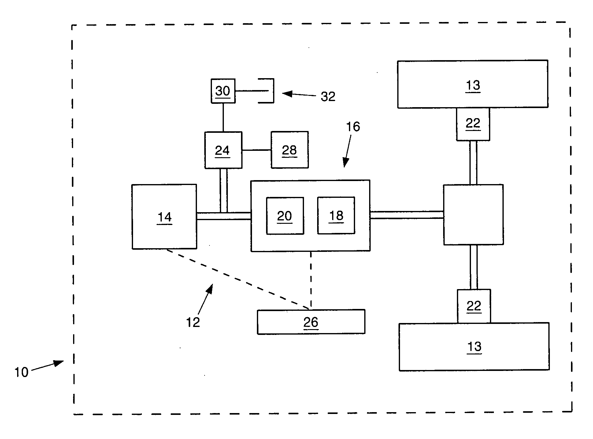
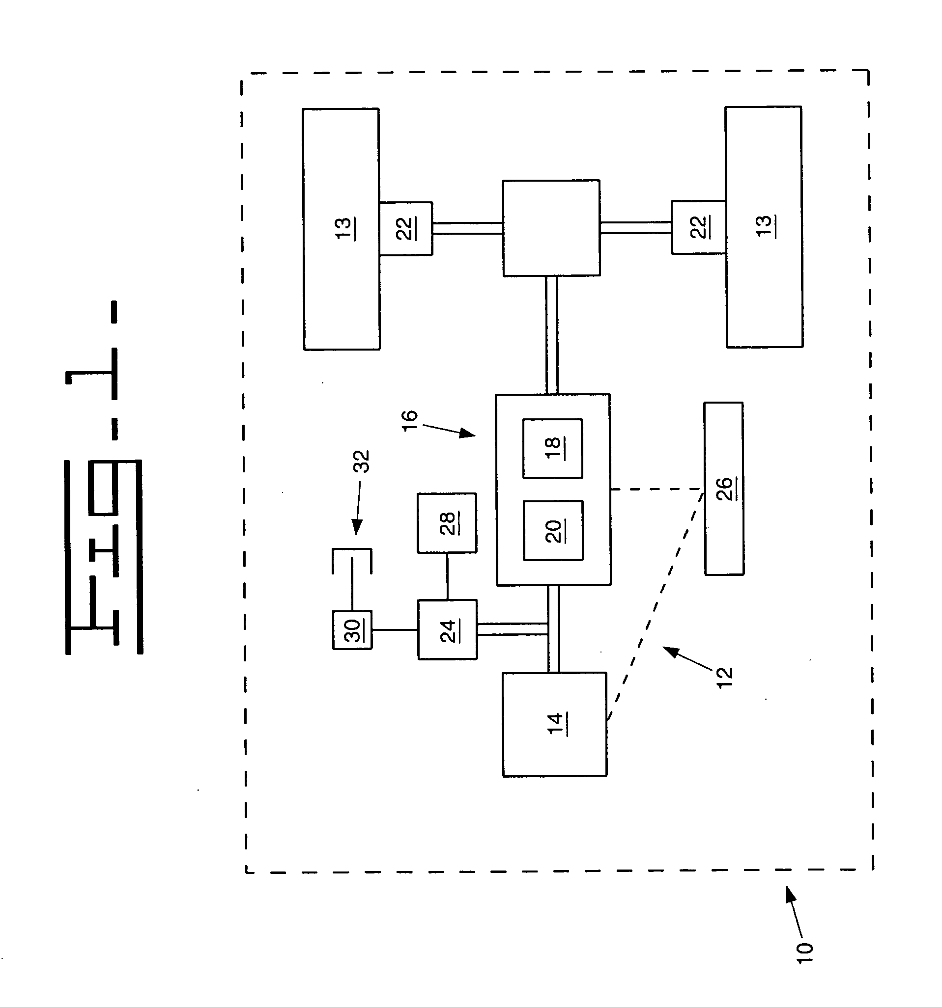
[0014]FIG. 1 schematically illustrates a propelled machine 10 having a hydromechanical drive 12 in accordance with an exemplary embodiment of the present disclosure. The hydromechanical drive 12 may be used in any type of machine having wheels or sprockets 13 for propelling the propelled machine 10. For example, the hydromechanical drive 12 may be used on a dozer machine having tracks propelled by sprockets 13 coupled to the hydromechanical drive 12.

[0015]As illustrated in FIG. 1, the hydromechanical drive 12 may include an internal combustion engine 14 coupled to provide power to a hydromechanical transmission 16. The hydromechanical transmission 16 may include a hydrostatic system 18 having a pump and motor (not shown) and a mechanical system 20, which may be a planetary type transmission (not shown). Brak...


PUM


Abstract

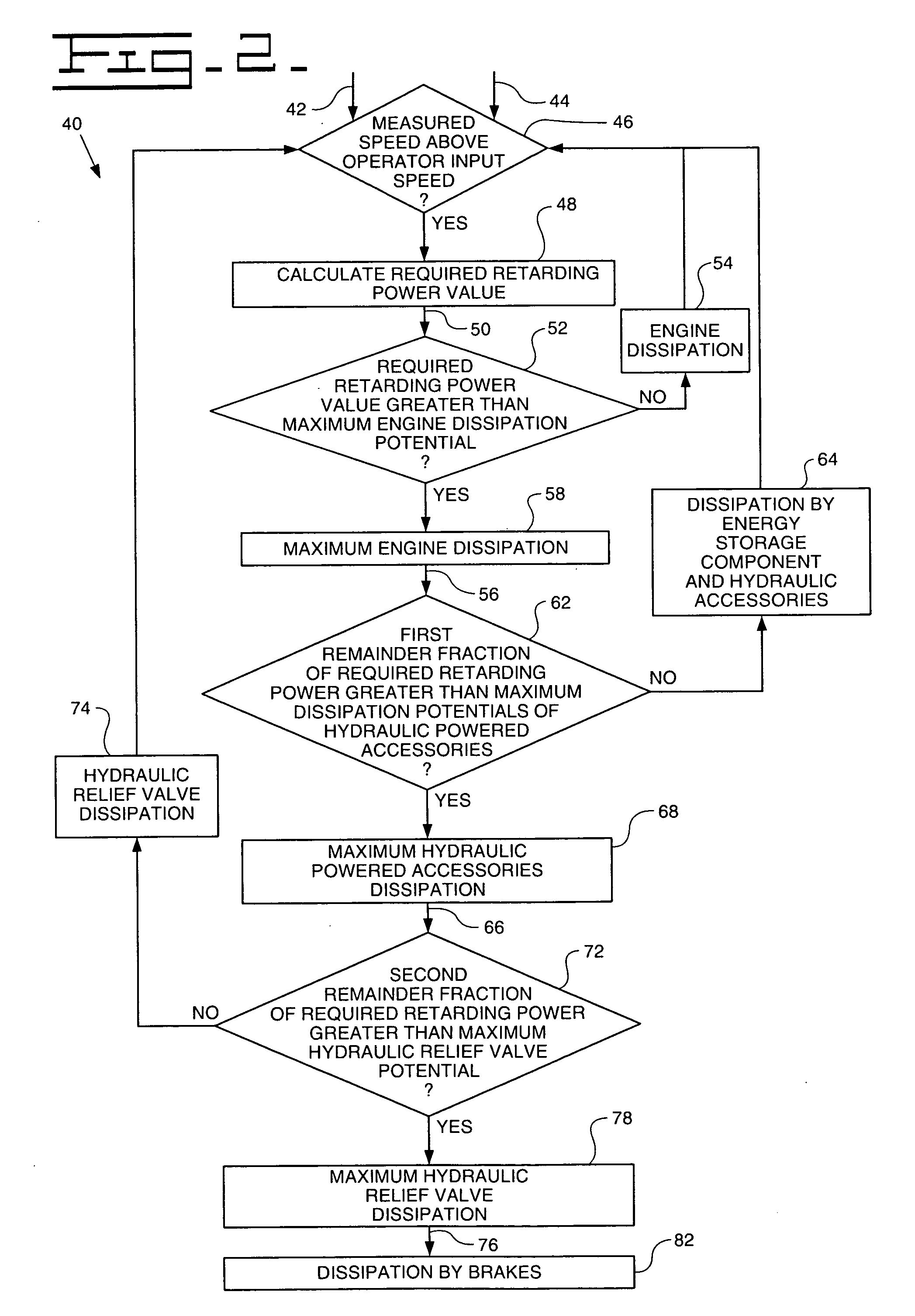
A method of dissipating power in a propelled machine having a hydromechanical transmission includes converting undesired power to retarding power, and driving an engine with at least a portion of the retarding power prior to substantially dissipating power with any other power-dissipating device.

Description

TECHNICAL FIELD [0001]This invention relates to hydrostatic drive systems for propelled machines, and more particularly to retarding control for propelled machines having a hydromechanical drive.BACKGROUND [0002]Retarding performance of a propelled machine relates to the capability of the propelled machine to dissipate undesired power or energy. Such undesired power may include the power of the machine when moving at an undesired speed and / or direction. For example, undesired power of the machine can result from travel down an incline, or exist just after the initiation of a directional shift of the machine from a reverse direction to a forward direction, or vice versa. Conventional propelled machines having mechanical transmissions and drivetrains dissipate portions of undesired power as heat by way of mechanical clutches, torque converters and the engine.[0003]U.S. Pat. No. 5,954,799 to Bernd Dietzel (“the '799 patent”) discloses a propelled vehicle having a process for influencin...

Claims


Application Information

Patent Timeline
Patent Type & Authority Applications(United States)
IPC IPC(8): B60K25/10
CPCB60W10/103B60W10/184B60W30/18136B60W30/18109B60W10/30
Inventor KURAS, BRIAN D.SOPKO, THOMAS M.DEMARCO, FRANK A.CRONIN, MICHAEL G.
Owner CATERPILLAR INC
Learn More