Light emitting apparatus, display apparatus and method for controlling light emitting apparatus

a technology of light emitting apparatus and display apparatus, which is applied in the direction of discharge tube/lamp details, luminescent compositions, discharge tubes luminescnet screens, etc., and can solve the problem of increasing power consumption, deteriorating color reproducibility, and reducing the emission intensity of a red component perceived by the human eye as the backligh

Inactive Publication Date: 2007-12-13
LEDCOMM LLC
View PDF6 Cites 68 Cited by
  • Summary
  • Abstract
  • Description
  • Claims
  • Application Information

AI Technical Summary

Benefits of technology

[0012]An object of the present invention is to provide (I) a light emitting apparatus which can obtain both of or select one of (i) as high a color reproducibility as possible while securing the reliability of the apparatus and (ii) necessary luminance in accordance with conditions, such as an o...

Problems solved by technology

Further, since the emission intensity itself of the AlGaInP based red LED decreases as the temperature rises, two disadvantageous factors occur, and this leads to decrease in the emission intensity of a red component perceived by the human eye as the backlight.
In light of the coloring of the backlight, this decrease relatively increases percentages of blue and green components, so that the color reproducibility is deteriorated.
However, this causes problems, such as increase in power consumption, increase in the amount of heat generated, and dec...

Method used


Image

  • Light emitting apparatus, display apparatus and method for controlling light emitting apparatus
  • Light emitting apparatus, display apparatus and method for controlling light emitting apparatus
  • Light emitting apparatus, display apparatus and method for controlling light emitting apparatus

Examples


embodiment 1

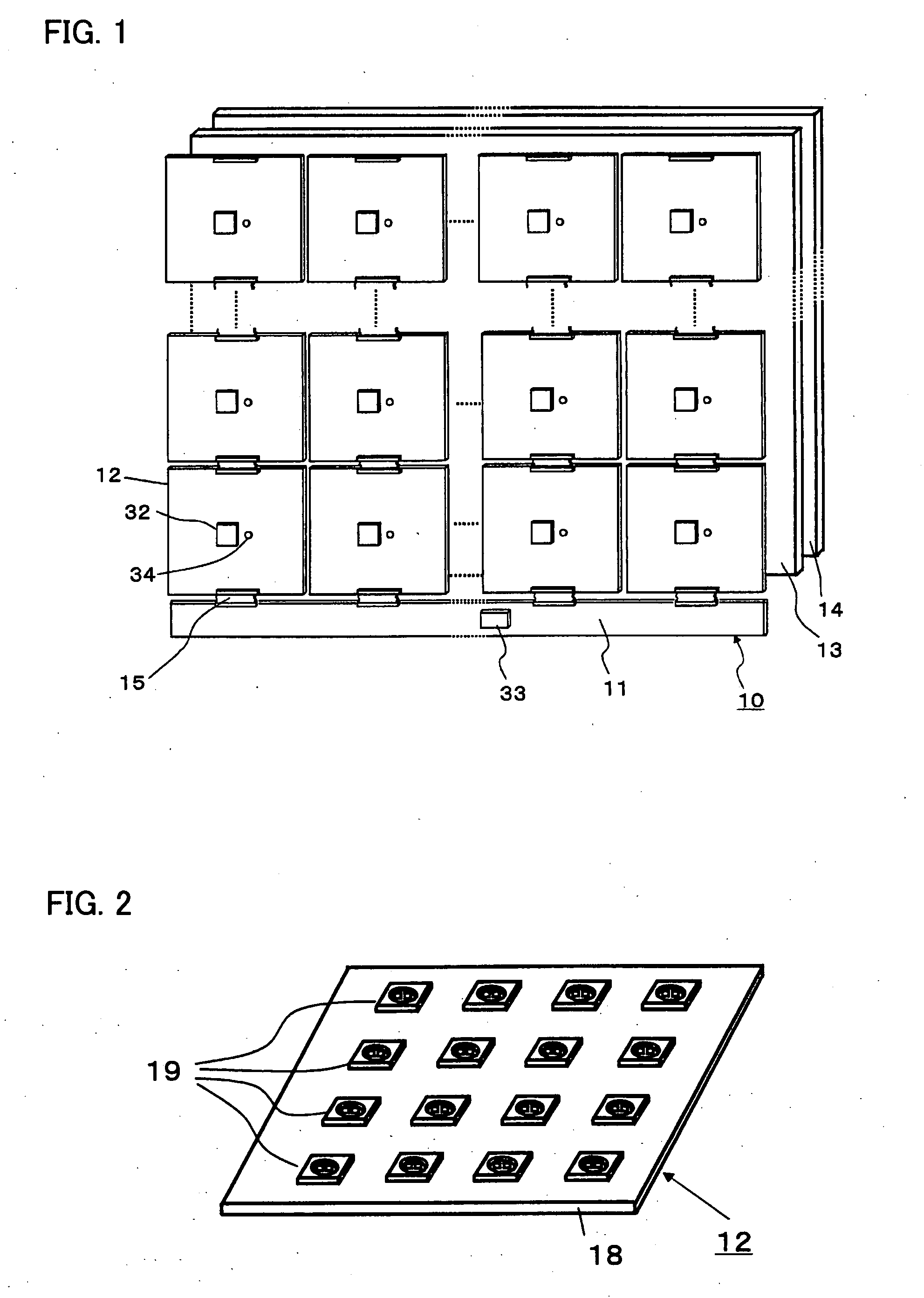
[0039]FIG. 1 is a block diagram of a liquid crystal display apparatus 10 of Embodiment 1. A plurality of backlight tiles 12 illuminate a liquid crystal panel 14 via a diffuser plate 13. A drive circuit 32 is mounted on a back surface (surface shown in FIG. 1) of the backlight tile 12. In addition, a temperature sensor 34 may be mounted. Note that the temperature sensor 34 is not used in the first operation described below. Moreover, the temperature sensor 34 may be mounted on each backlight tile 12, or may be mounted on only one backlight tile 12 or representative backlight tiles 12. The drive circuit 32 and the temperature sensor 34 are connected via a cable 15 to a control circuit 33 provided on a control substrate 11 common to the backlight tiles 12. Note that it is possible to configure the display apparatus even if the liquid crystal panel 14 is replaced with a non light emitting image display panel, such as an MEMS (microelectromechanical system) panel or a shutter panel which...

embodiment 2

[0077]In Embodiment 2, the LED group 19 used in Embodiment 1 is replaced with an LED group 59, and both the green LED chip and a green light emitting phosphor are used for the green color. Moreover, the color sensor is used to control the ratio between the light from the LED chip and the light from the phosphor to obtain the color balance. Thus, it is possible to obtain a display apparatus which uses the red light emitting phosphor having excellent temperature characteristics and the green light emitting phosphor having excellent light emitting efficiency to obtain high luminance even at high temperature.

[0078]FIG. 17(a) is a top view of the LED group 59, and FIG. 17(b) is its cross-sectional diagram. A first blue LED chip 61A, a green LED chip 62, a second blue LED chip 61B and a red LED chip 63 are mounted on a package 60. Green light emitting phosphors 64 are dispersed in a first resin 68A which covers the first blue LED chip 61A, and red light emitting phosphors 65 are dispersed...

embodiment 3

[0089]In Embodiment 3, one blue LED chip excites two types of phosphors. Therefore, the number of chips in Embodiment 3 is reduced by 1 as compared with that in Embodiment 2. Embodiment 3 only explains the LED group and its operation which are different from those in Embodiment 2. Same reference numerals are used for the members having the same functions as the members in the above embodiments.

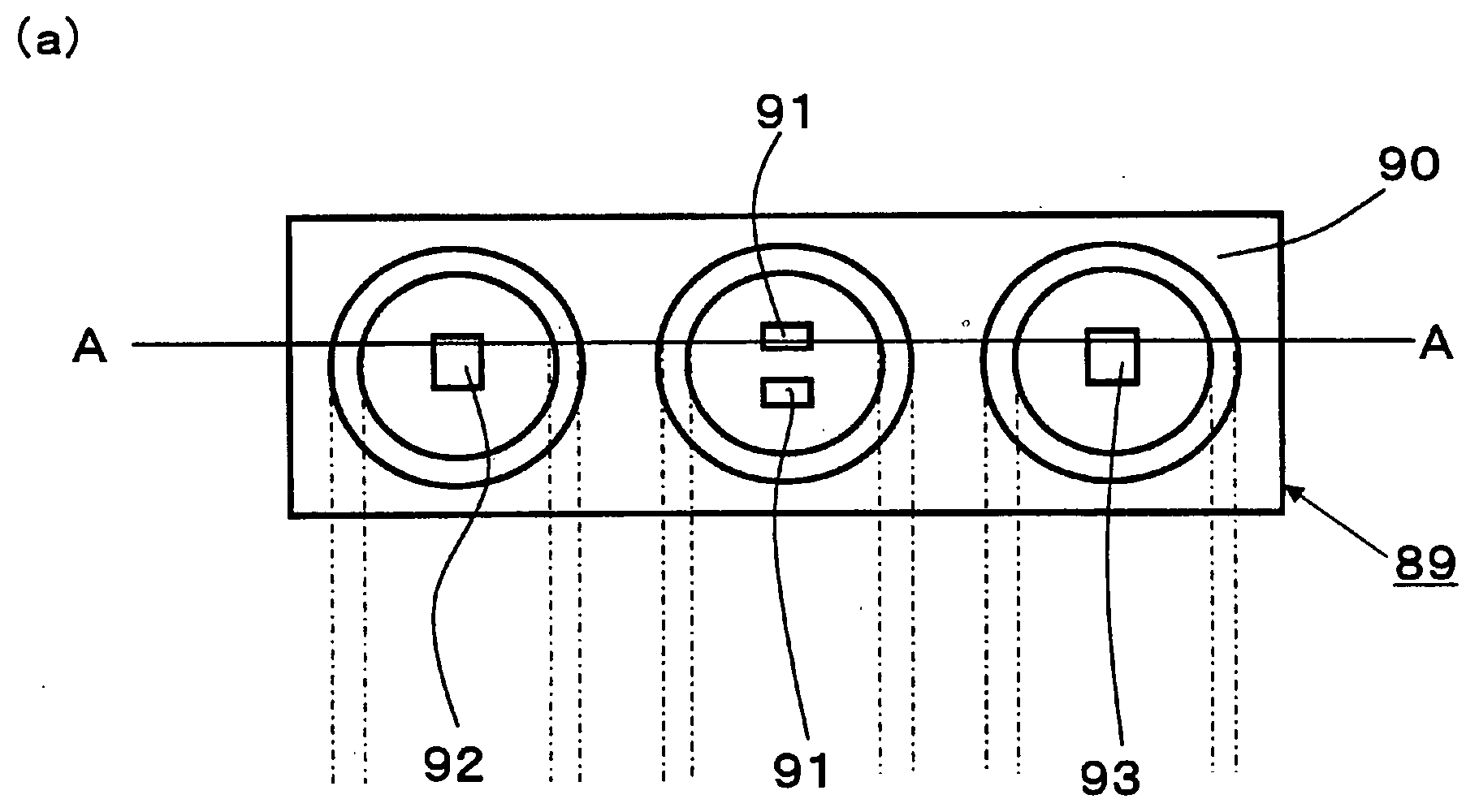
[0090]As shown in FIG. 20(a) that is the top view and FIG. 20(b) that is the cross-sectional diagram, an LED group 89 is obtained by mounting two blue LED chips 91, a green LED chip 92 and a red LED chip 93 on a package 90. A resin 98 is filled so as to seal the blue LED chips. The resin 98 has two layers. Red light emitting phosphors 95 are dispersed in one layer which is closer to the blue LED chips 91, and green light emitting phosphors 94 are dispersed in another layer which is away from the blue LED chips 91. This is preferable since the percentage of light emission which is from the gree...


PUM


Abstract

In a light emitting apparatus using LEDs, luminance and chromaticity of the LED changes largely due to a temperature change. Meanwhile, by using phosphors, it is possible to improve the stability of the luminance and chromaticity against the temperature change. However, color reproducibility of the light emitting apparatus decreases. Therefore, the light emitting apparatus includes a first LED, a second LED, a first phosphor which is excited by the second LED and emits light whose color is the same as or similar to a color of light emitted from the first LED, and a control circuit which controls a ratio between an emission intensity of the first LED and an emission intensity of the second LED.

Description

[0001]This Nonprovisional application claims priority under 35 U.S.C. § 119(a) on Patent Application No. 148986 / 2006 filed in Japan on May 29, 2006, the entire contents of which are hereby incorporated by reference.FIELD OF THE INVENTION[0002]The present invention relates to a light emitting apparatus which uses LEDs and phosphors, a non light emitting display apparatus which includes the light emitting apparatus as a light source, and a method for controlling the light emitting apparatus.BACKGROUND OF THE INVENTION[0003]In recent years, developments of a configuration using, as a light source of a backlight used in a liquid crystal display apparatus, a light emitting diode (hereinafter referred to as “LED”) instead of a conventional cold cathode fluorescent tube (hereinafter referred to as “CCFL”) have been advanced. Especially, as compared with a conventional CCFL tube backlight, an LED backlight which uses LEDs of three primary colors (red, green and blue) is characterized in tha...

Claims


Application Information

Patent Timeline
IPC IPC(8): H01J1/62H01J63/04H01L33/32H01L33/50H01L33/56H01L33/60
CPCC09K11/0883C09K11/7721C09K11/7734H05B33/14H01L25/0753H01L33/50H05B33/0857C09K11/7774H01L2924/0002H05B45/28C09K11/77348H01L2924/00
Inventor MORIMOTO, TAIJIWATANABE, MASANORI
Owner LEDCOMM LLC
Why Eureka
Try Eureka