Head coil arrangement with an adjustable neck-engaging portion for use in a magnetic resonance apparatus

a magnetic resonance apparatus and neck-engaging portion technology, applied in the direction of instruments, using reradiation, diagnostic recording/measuring, etc., can solve the problems of pressure marks, difficult to achieve a suitable shape, uncomfortable positioning of the head, etc., and achieve the effect of improving the signal-to-noise ratio

Inactive Publication Date: 2007-12-13
SIEMENS HEALTHCARE GMBH
View PDF7 Cites 6 Cited by
  • Summary
  • Abstract
  • Description
  • Claims
  • Application Information

AI Technical Summary

Benefits of technology

[0008] An object of the present invention is to provide a head coil arrangement that is suitable for a large number of neck shapes and has an improved signal-to-noise ratio.
[0010] In the head coil arrangement according to the invention, the shape of the housing in the region designated for the subject's neck can be modified by a user, and the housing can thus be shaped to the individual neck of the received head. Thus an improved signal intensity for each patient and therefore a better signal-to-noise ratio is achieved because the individual coils are closer to the patient's head. For an individual positioning of the head, the housing part advantageously can be lowered in such a way that when positioning the head a substantially uniform region results and the head can thus be individually positioned. If the head is in a suitable position, the movable and / or moldable housing part can be adjusted to the actual neck shape by a user.
[0011] According to the invention, a number of movable and / or moldable housing parts can be provided in the neck region in order to increase the possibilities for adjustment to different neck shapes.
[0014] In an embodiment, the housing part is designed so it can be moved and / or bowed toward the interior of the head coil arrangement. Both an embodiment in which the housing part is fixed in terms of shape may be moved toward the neck of a patient, and an embodiment in which the housing part can change its shape and can thus be bowed, are therefore possible. The housing part is preferably in a lowered position when it is not moved or bowed toward the inside of the head coil arrangement, i.e. the local coil arrangement has a substantially uniform and flat internal surface.
[0015] Depending on position and / or shape, the housing part of the head coil arrangement according to the invention may overlap another housing part at least partially, particularly if a moldable housing part is used which nevertheless has a fixed surface. This type of overlap occurs in a lowered position for example. It may be expediently for the overlapping region of the housing part to be moved at least partially into a receiving device or holding device, which can be arranged or embodied on or in another housing part. In this case, a receiving device may be provided underneath the other housing part, for example, into which the housing part slides. This does not have to be closed, but can also form a simple holding device.
[0023] In order to enhance the patient's comfort, a pressure damper may be provided on the inside of the housing part, such as a cushion. The housing part that is usually designed somewhat firmer, then does not exert any direct pressure on the patient's head during shaping, as the patient is advantageously cushioned by the pressure damper in such a way that, in spite of its proximity with the coils, the head is comfortably positioned.

Problems solved by technology

Due to the widely varying neck shapes of different patients, for example thick necks, thin necks, short necks, long necks, etc., it is particularly difficult to achieve a suitable shape with the closest possible proximity to the patient's head.
This is disadvantageous however, since the fixed neck shape may come into contact with the subject at a location that is too high for some patients, which may lead to pressure marks or an uncomfortable positioning of the head.
On the other hand, the fixed neck shape may extend too low for other patients, leading to poor signal intensity because of the larger-than-optimal spacing that then exists.
A further disadvantage of a fixed neck shape of this kind is that the position of the head within the head coil arrangement is fixed, with the result that an individual positioning of the head is not possible.
Particularly when developing new head coil arrangements with a relatively large number of individual coils, it is necessary to bring the individual coils close to the region of the body to be examined, because, due to the relatively small coils, the intensity of the receiving signal is lower and a poorer signal-to-noise ratio is thus achieved with the same spacing.

Method used


Image

  • Head coil arrangement with an adjustable neck-engaging portion for use in a magnetic resonance apparatus
  • Head coil arrangement with an adjustable neck-engaging portion for use in a magnetic resonance apparatus
  • Head coil arrangement with an adjustable neck-engaging portion for use in a magnetic resonance apparatus

Examples


Embodiment Construction

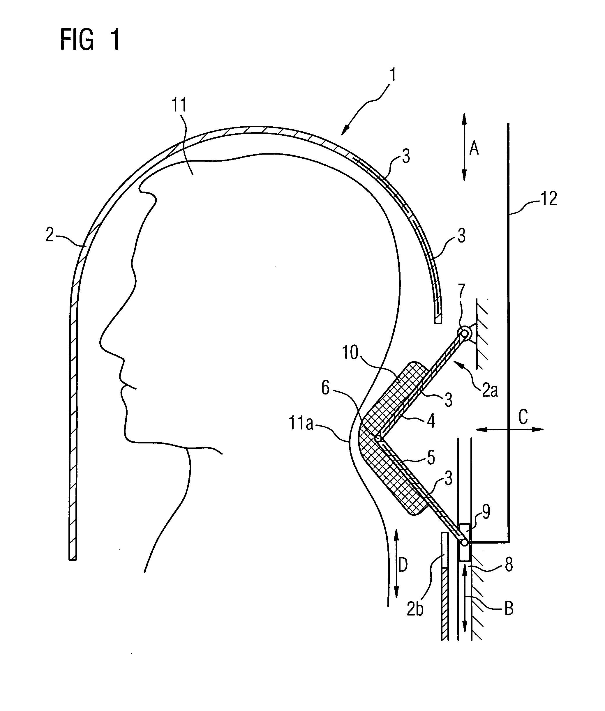
[0028] Several exemplary embodiments of a head coil arrangement according to the invention are shown below. All the same components in the various drawings have the same reference numbers.

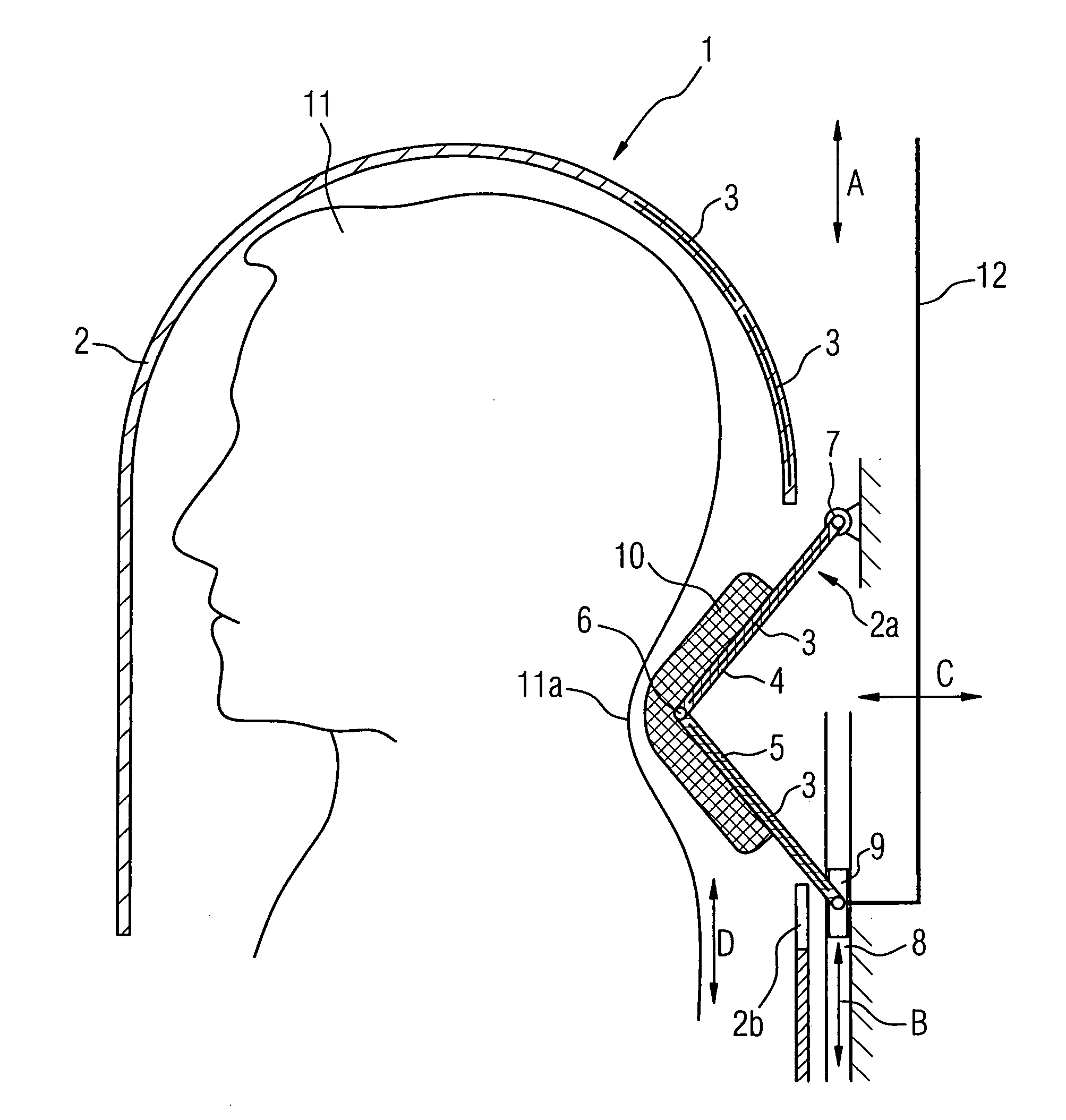
[0029]FIG. 1 shows a head coil arrangement 1 according to a first exemplary embodiment. This arrangement has a housing 2 in which the individual coils 3 are arranged, of which only some are illustrated in outlines. For clarity, the individual coils are not illustrated in the other drawings, but these coils are of course present in every exemplary embodiment. The coils 3 do not have to be arranged within the housing 2. They may also be provided or arranged on the housing 2. In the region designated for the patient's neck, a movable, moldable housing part 2a is provided. The housing part 2a is formed by housing sections 4 and 5 that are connected so as to allow them to swivel toward each other by means of a joint 6. On one side, the housing section 4 is positioned so that it can be swiveled by means...


PUM


Abstract

Head coil arrangement for a magnetic resonance apparatus has a housing with a number of coil elements arranged in or on the housing, and the housing has at least one movable and / or moldable housing part (2a) for adjustment to different neck shapes in the region designated for the neck of a patient.

Description

BACKGROUND OF THE INVENTION [0001] 1. Field of the Invention [0002] The present invention relates to a head coil arrangement of the type having a housing in or on which a number of coil elements are arranged. [0003] 2. Description of the Prior Art [0004] Head coil arrangements of this type are known and are used in magnetic resonance devices as high-frequency transmitting and receiving coils. If the coils operate in a receiving mode, the size of the coils in relation to the size of the examination subject plays a decisive role in the resulting signal-to-noise ratio. The signal-to-noise ratio is optimal if the coils rest as close as possible to the surface of the subject, in this case the head. [0005] This is particularly critical when capturing images of regions close to the patient's neck, such as the cerebellum for example. Due to the widely varying neck shapes of different patients, for example thick necks, thin necks, short necks, long necks, etc., it is particularly difficult t...

Claims


Application Information

Patent Timeline
Patent Type & Authority Applications(United States)
IPC IPC(8): G01V3/00
CPCA61B5/055G01R33/3415G01R33/341G01R33/34084A61B5/702
Inventor DRIEMEL, DANIEL
Owner SIEMENS HEALTHCARE GMBH
Why Eureka
Try Eureka